Fig.
78-53
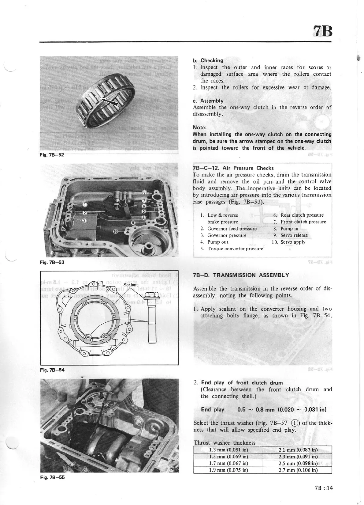
Fig.
78-54
Fig.
78
-6
6
7B
b. Checking
I.
Inspect
the
outer
and
inner
races
fo
r scores
or
da
maged surface area where
the
rollers
contact
the
races.
2. Inspect
the
rollers for excessive wear
or
damage.
c. Assembly
Assemble
the
one
-way
clutch
in
the
reverse
order
of
disassembly.
Note:
When installing
the
one-way
clutch
on
the
connecting
drum,
be
sure
the
arrow
stamped
on
the
one-way
clutch
is
pointed
toward
the
front
of
the
vehicle.
7B-C
-12.
Air Pressure Ch
ecks
To make
the
air pressure checks, drain
the
transmission
fluid
and
remove
the
oil
pan
and
the
control
valve
body
assembly.
The
inoperative units
ca
n
be
located
by
introducing
air pressure
into
the
various transmission
case passages (Fig.
7B
-53
).
1.
Low
& reverse
6.
Rear clutch pressure
brake pressure
7.
Fro
nt
clutch pressure
2.
Governor feed pressure 8.
Pump
in
3. Governor pressure 9. Servo release
4. Pump
out
IO. Servo apply
5. Torque converter pressure
78-0.
TRANSMISSION ASSEMBLY
Assemble
the
transmission in the reverse
order
of
dis-
assembly,
noting
the
following p
oints
.
1. Apply sealant
on
the
converter housing
and
two
attaching
bolts flange, as shown
in
Fig. 7
B-
54.
2.
End
play
of
front
clutch
drum
(Clearance
between
the
front
clutch
drum
and
the
connecting shell.)
End
play
0.5 - 0.8
mm
(0.020 - 0.031 in)
Select
the
thrust
washer (Fig.
7B-57
Q))
of
t
he
thick-
ness
that
will
allow specified end play.
Thrust
washer thickness
1.3
mm
(0.051 in) 2.1
mm
(0.083
in)
1.5
mm
(0.059
in)
..
2.3
mm
(0.091
in)
1.7
mm
(0
.
067
in)
2.5
mm
(0.098
in)
1.9
mm
(0.075 in) 2.7
mm
(0.106 in)
7B:
14
,.