Fig.
16-36
•
15-
1.
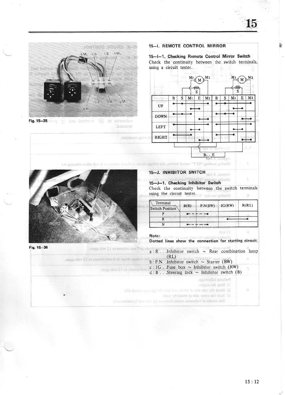
REMOTE CONTROL MIRROR
15-1-1.
Checking Remote Control
Mirror
Sw
itch
Check
the continuity between the switch terminals,
u
si
ng a circuit tester.
UP
DOWN
LEFf
RIG
HT
15-J.
INHIBITOR
SWITCH
15-J-1.
Checking Inhibitor Switch
Check
the continuity between the switch terminals
using the circuit test er.
I\
Terminal
B(B)
P.
N(BW)
IG(RW)
I
R(RL)
Switch
Position\
p
--
--
R
N
--
~-
-
Note:
Dotted
lines
show the connection for starting circuit.
a : R . . .Inhibitor switch
-
Rear combination lamp
(RL)
b: P.N
..
Inhibitor switch -
Starter (
BW)
c :
I G
..
Fuse box
-
Inhibitor switch (RW)
d : B
...
Steering lock -
Inhibitor switch
(8)
15
: 12