1
Fig.
1-9
vvnmn
17nvnC0.67m
)
Chai
n adjuster
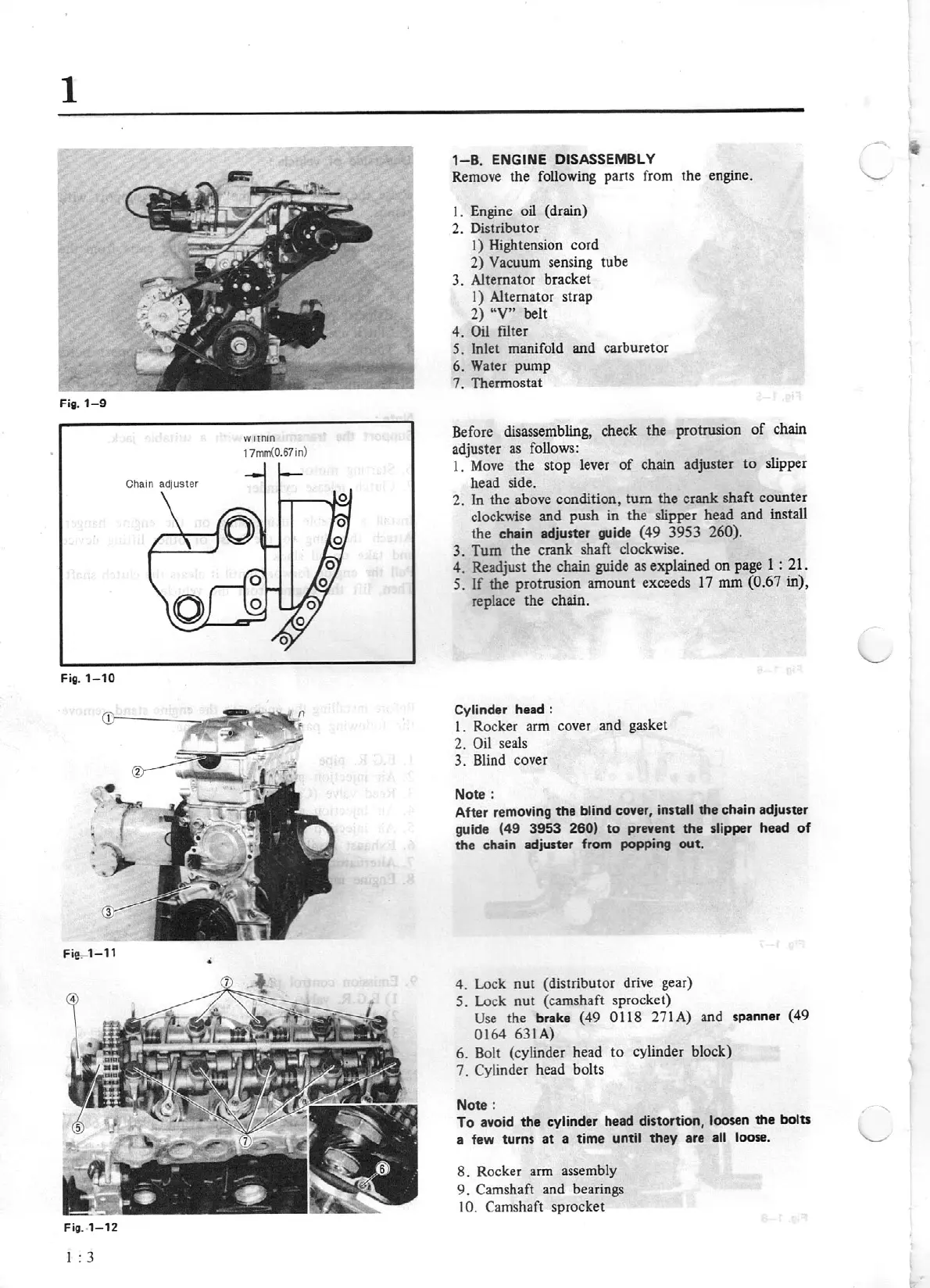
Fig. 1-
10
Fie.
1-11
•
Fig.
1-12
I : 3
1-B
.
ENGINE
DISASSEMBLY
Remove the following parts from the engine.
I.
Engine oil (drain)
2. Distributor
1) Hightension cord
2)
Vacuum sensing tube
3. Alternator bracket
I)
Alternator strap
2)
"V"
belt
4.
Oil
filter
S.
Inlet manifold and carburetor
6.
Water pump
7.
Thermostat
Before disassembling, check the protrusion
of
chain
adjuster
as
follows:
1.
Move the stop lever
of
chain adjuster
to
slipper
head side.
2.
In
the above condition,
tum
the crank shaft counter
clockwise and push in the slipper head and install
the chain adjuster
guide
(49 3953
260).
3.
Tum
the crank shaft clockwise.
4.
Readjust the chain guide
as
explained
on
page
1 :
21.
S.
If
the protrusion amount exceeds 17
mm
{0.67
in),
replace the chain.
Cylinder head :
I.
Rocker arm cover and gasket
2.
Oil
seals
3. Blind cover
Note :
After removi
ng
the
blind
cover,
install
the
chain adjuster
guide
(49 3953
260)
to
prevent
the
slipper
head
of
the chain adjuster from
popping
out.
4.
Lock
nut
(distributor drive gear)
S.
Lock nut (camshaft sprocket)
Use
the brake
(49
0118
271A) and spanner (49
0164
631A)
6. Bolt (cylinder head
to
cylinder block)
7. Cylinder head bolts
Note :
To
avoid
the
cylinder head distortion, loosen
the
bolts
a few turns
at
a time
until
they
are
all loose.
8. Rocker arm assembly
9.
Camshaft and bearings
10. Camshaft sprocket
-