9
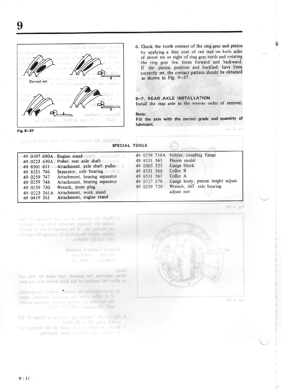
Correct set
Fig.
9-
37
49
0107 680A
49
0223 630A
49
8501
631
49
8531 746
49
0259
747
49
0259
748
49
0259 730
49
0223
561A
49
0419
561
9 :
11
6. Check the tooth contact
of
the ring gear and pinion
by applying a thin coat
of
red lead on
both
sides
of
about six or eight
of
ri
ng
gear teeth and rotating
the ring gear
few
times forward and backward.
If
the pinion position and backlash have been
correctly set, the contact pattern should
be
obtained
as shown in Fig.
9-37
.
9-F.
REA
R AX LE
INS
TALLAT
ION
Install the rear axle in the reverse order
of
removal.
Note:
F
ill
the
axle
w
ith
t
he
correct grade and q
uantity
of
lubricant.
SP
EC
IA L TOOLS
Engine stand
Puller,
rear axle shaft
Attachment, axle shaft puller
Separator, axle bearing
Attachme
nt
, bearing separator
Attachment, bearing separator
Wren
ch, drain plug
Attachment, work stand
Attachment, engine stand
•
49
0259 710A
49
8531 565
49
0305 555
49 8531 568
49 8531 567
49
0727 570
49
0259 720
Holder, coupling
flange
Pinion
model
Gauge block
Coller B
Coller
A
Gauge body, pinion height"
adjust
Wren
ch, diff. side bearing
adjust nut