Fig, 1-
28
L
--1;--[-_ ----
----r-r-
___
;g
-----r+-_
_
IN
Fig.
1-30
Fig. 1- 31
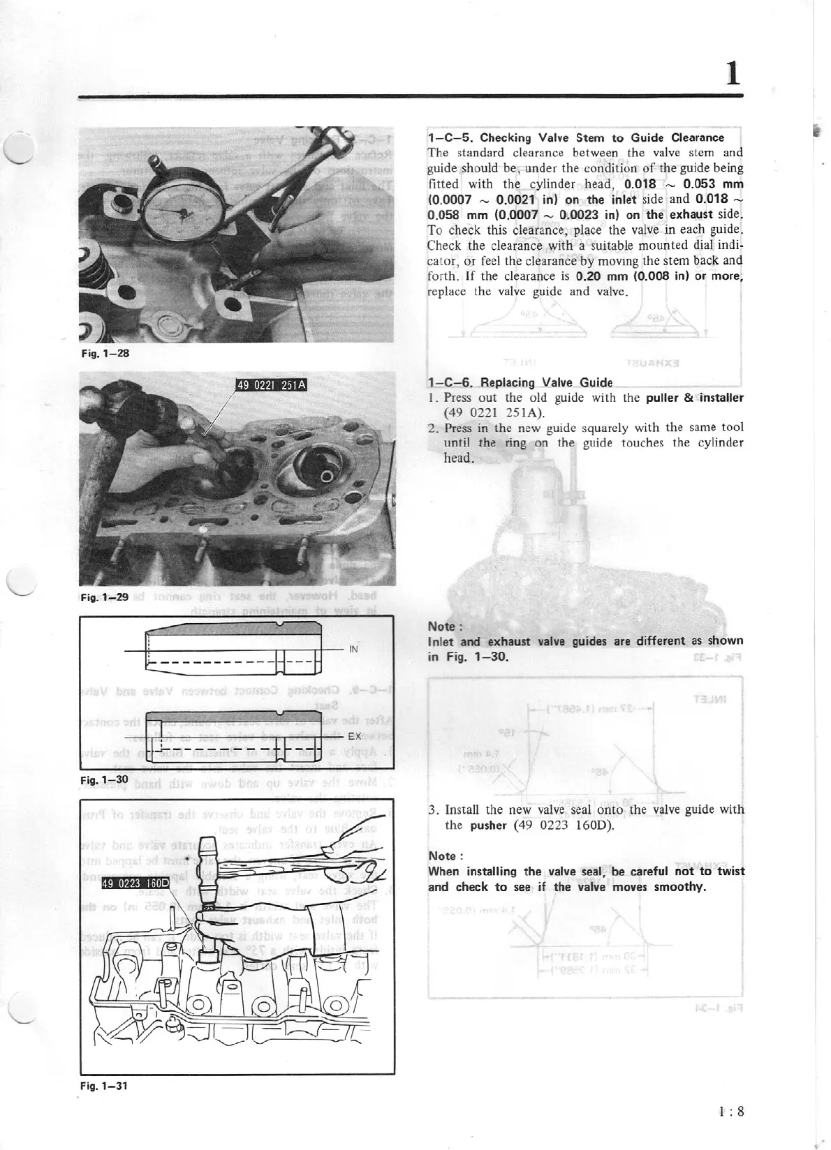
1-C
-5
. Checking Valve Stem
to
Guide Clearance
The standard clearance between the
va
l
ve
stem and
guide should be, under the condition
of
the guide being
fitted with the cylinder head, 0.018 - 0.053 mm
(0.
0007
- 0.0021 in)
on
the
inlet side and 0.018 -
0.0
58
mm (0.
0007
~
0.0023 in) on
the
exhaust side.
To
check this clearance, place the
va
lv
e in each guide:
Check the clearance with a suitable mounted dial indi-
cator, or
feel
the clearance by moving the stem back a
nd
forth. If the clearance
is
0.
20
mm (0.008
in)
or
more;
replace the valve guide and valve.
1
-C-6.
Replacing Valve Guide
I. Press
out
the old guide with the puller & installer
(49 0221 251A).
2.
Press
in
the new guide squarely with the same tool
until the ring on the guide touches the cy
li
nder
head.
Note:
Inlet and exhaust v
al
ve guides are different as shown
in
F
ig.
1-30
.
3. Install the new
va
l
ve
seal
onto
the
va
l
ve
guide with
the
pusher (49 0223 160D).
Not
e:
When installing
the
va
lve seal, be careful
not
to
twist
and check
to
see if the valve moves smoothy.
I : 8