Fig.
13
-
19
Fig. 1
3-
20
Fig
.
13
- 21 •
Fig.
13-22
13
1
3-
B-4
.
Installing
Front Suspension Arm
Install the suspension arm in the reverse
order
of
removing.
No
te
:
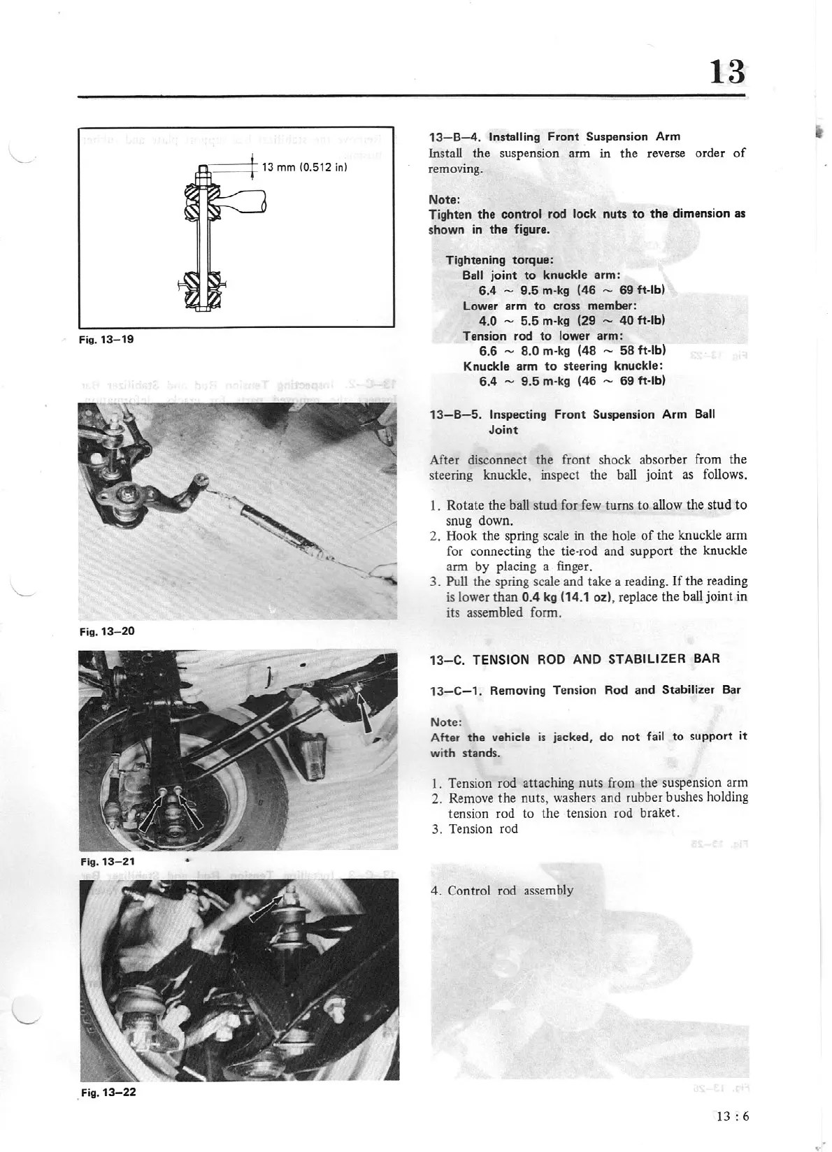
Tighten
the
control
rod
lock
nuts
to
the
dimension as
shown in
the
figure.
Tightening torque:
Ball
joint
to
knuck
le
arm:
6.4
-
9.5
m·kg
(46
-
69
ft-lb)
Lower arm
to
cross member:
4.0 -
5.5
m-
kg
(29
-
40
ft-lb)
Tension rod
to
lower arm:
6.6
-
8.0
m
-kg
(48
-
58
ft-lb)
Knuckle
arm to steeri
ng
knuckle:
6.4
-
9.5
m·kg
(46
-
69
ft-lb)
13-
B- 5.
Inspecting
Front
Suspension Arm
Ball
Joint
After disconnect the front shock absorber from the
steering knuckle, inspect the ball joint
as
follows.
1. Rotate the ball stud for few turns
to
allow
th
e stud to
snug dow
n.
2.
Hook the spring scale in the hole
of
the
kn
uckle arm
for connecting the tie-rod and support the knuckle
arm by placing a finger.
3.
Pull
the spring scale and take a reading.
If
the reading
is
lower than
0.4
kg
(1
4.
1 oz), replace the ball joint in
its assembled form.
13-
C.
TENSION ROD
AND
STABILIZER
BAR
13
- C
-1
. Removing Tension Rod and
Stabilizer Bar
Note:
After the vehic
le
is
jacked,
do
not
fa
il
to
support
it
with stand
s.
I.
Tension rod attaching nuts from the suspension arm
2. Remove the nuts, washers and rubber bushes holding
tension rod to the tension rod braket.
3. Tension rod
4. Control rod assembly
13
: 6