Fig.
10A
-
33
Fig.
10A
-
34
Fig.10A
-
36
•
Fig.
10A
-
36
lOA
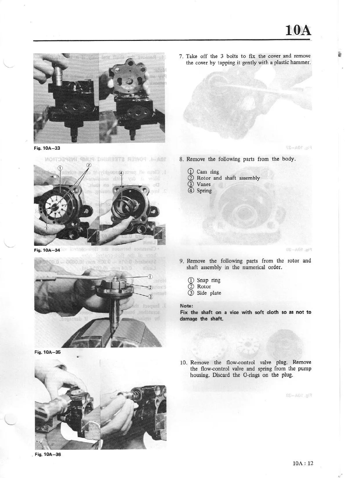
7. Take
off
the 3 bolts
to
fix
the cover and remove
the co
ver
by tapping it
ge
ntly with a plastic hammer.
8.
Remove the following parts from the body.
<D
Cam
ring
~
Rotor and shaft assembly
Vanes
Spring
9.
Remove
the
following parts from the rotor and
shaft assembly in the numerical order.
~
Snap ring
Rotor
Side
plate
Notlt:
Fix the shaft on a vice with soft
cloth
so as
not
to
damage
the
shaft.
10.
Remove the flow-control
valve
plug. Remove
the flow-control valve and spring from the pump
housing. Discard the 0-rings on the plug.
lOA:
12