lOA
Fig.
10A-19
Fig
.1
0A-20
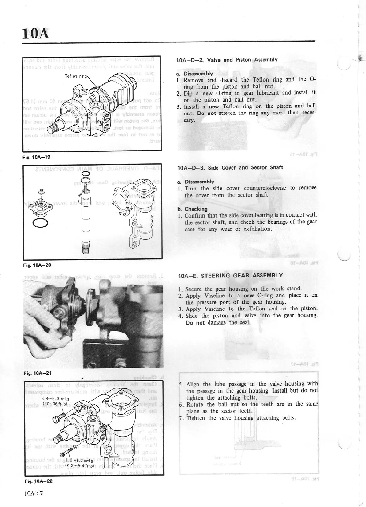
Fig.
10A-21
•
Fig.
10A
-2
2
lOA:
7
10
A-D-2.
Valve
and
Pi
ston Assembly
a.
Disassembly
l.
Rem
ove
and discard the Teflon ring and the 0 -
ring from the piston and ball nut.
2. Dip a new
0-ring in gear lubricant and install
it
on lhe piston and ball
nut.
3.
Install a new Teflon ring on the piston and
ball
nut.
Do
not
stretch the ring any more than
neces-
sary.
10A-
D-3.
Side
Cover and
Sector Shaft
a.
Di
sassembly
l.
Tum
the side cover counterclockwise to remove
the cover from the sector shaft.
b. Checking
l.
Confinn that the side cover bearing
is
in contact with
the sector shaft, and check the bearings
of
the gear
case
for
any wear or exfoliation.
10
A-E.
STEER
IN
G
GEAR
ASSEMBLY
1.
Secure the gear housing on the work stand.
2.
Apply Vaseline
to
a new
0-ring
and place
it
on
the pressure port
of
the gear housing.
3.
Apply Vaseline
to
the Teflon
seal
on
the
piston.
4.
Slide the piston and
valve
into the gear housing.
Do
not
damage the seal.
5.
Align
the lube passage
in
lhe valve housing with
the passage in the gear housing. Install
but
do
not
tighten the attaching bolts.
6.
Rotate the ball
nut
so the teeth are in the same
plane
as
the sector teeth.
7.
Tighten the valve housing attaching bolts.