Fi
g.10A
- 46
f ig.
10A-46
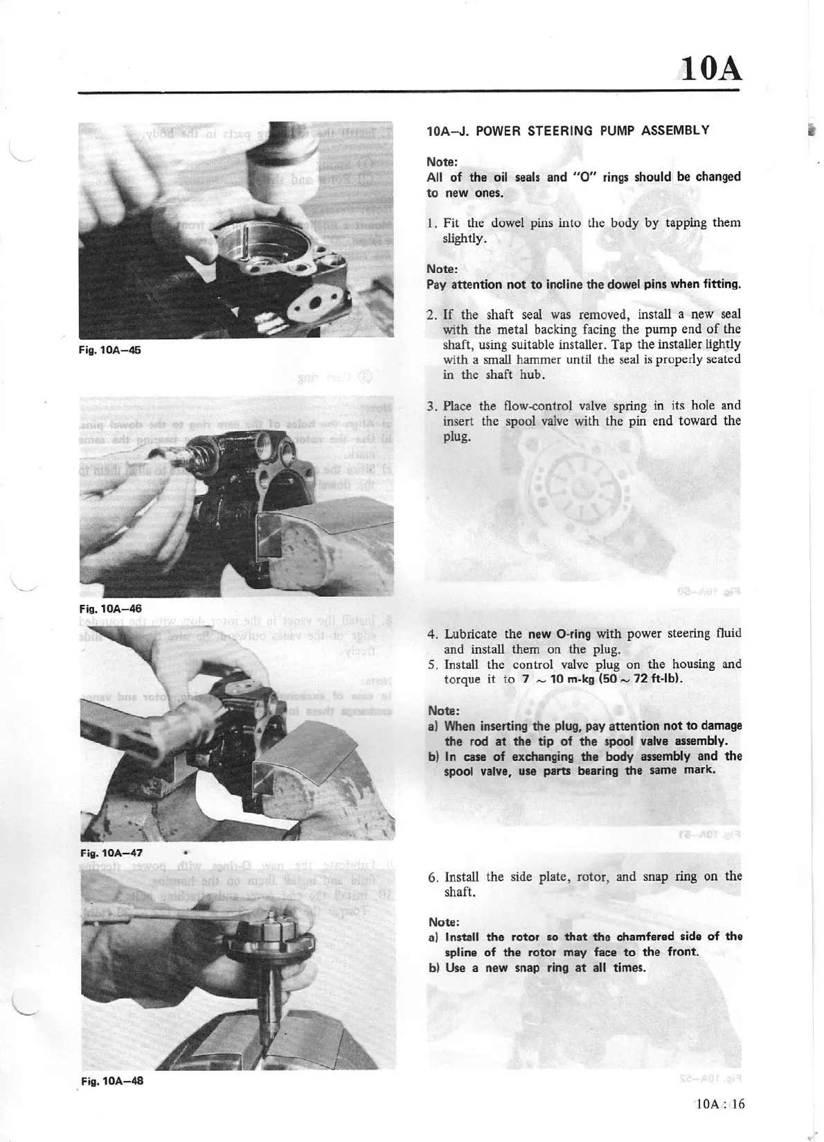
Fig.
10A-47
•
Fig.
10A-48
lOA
10A-
J.
POWER
STEERING
PUMP
ASSEMBLY
Note:
A
ll
of
the oil seals and
"O"
r
ing
s
should be changed
to
new ones.
1.
Fit the dowel pins into the body by tapping them
slightly.
Note:
Pay
atte
ntion
not
to
in
cline
th
e dow
el
pins when fitting.
2.
If
the shaft
seal
was removed, install a new seal
with the metal backing facing the pump end
of
the
shaft, using suitable installer. T
ap
the installer
li
ghtly
with a small hammer
until
the seal
is
properly seated
in the shaft hub.
3.
Place the flow-control
valve
spring in its hole and
insert the spool
valve
with the pin end toward the
plug.
4.
Lubricate the new
0 -ring with power steering fluid
and install them on the plu
g.
5.
Install the control
valve
plug
on
the housing and
torque
it
to
7
,...,
10
m-
kg
(50
,..,
72
ft
-lb).
Note:
a)
When inserting
th
e
plu
g,
pay a
tt
ention
not
to
damage
th
e rod
at
the tip of
the
spool valve
assembly.
b)
In
case
of
exchanging
the
body
assembly and the
spool
valve, use
parts
beari
ng
the same mark.
6.
Install the side plate, rotor, and snap ring on
th
e
shaft.
Note:
a)
Install
th
e rotor
so
th
at
th
e chamfered side
of
the
spline
of
the rotor
may
face
to
the front.
b)
Us
e
a new snap ri
ng
at
all
times.
lOA:
16