Fig. 11
-2
0
Fig.
11-21
Fig.
11-22
•
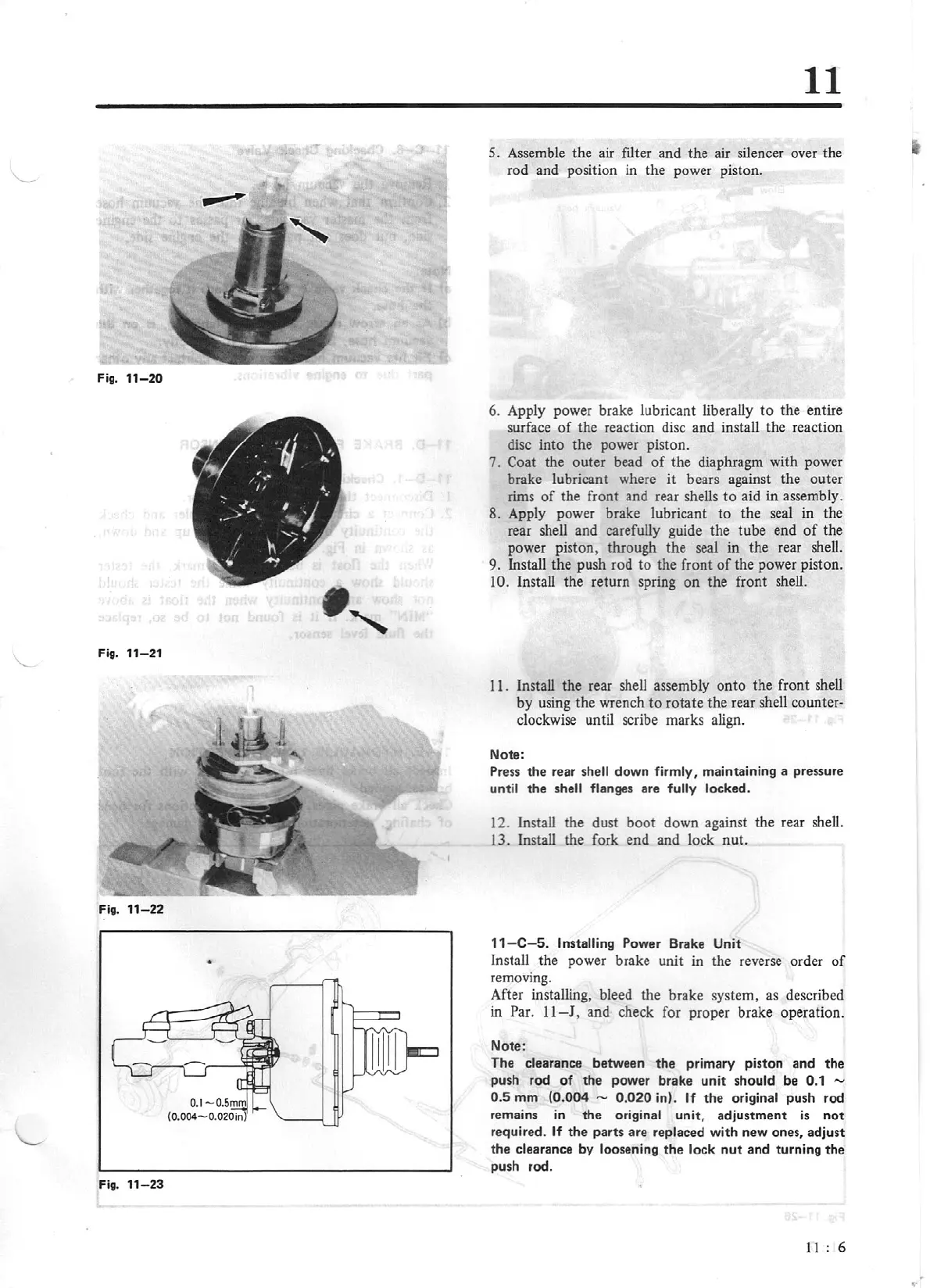
Fig. 11
-23
11
5. Assemble the air filter and the air silencer over the
rod and position in the power piston.
6. Apply power brake lubricant liberally
to
the entire
surface
of
the reaction disc and install the reaction
disc into the power piston.
7.
Coat the outer bead
of
the diaphragm with power
brake lubricant where
it
bears against the outer
rims
of
the front and rear shells
to
aid in assembly.
8. Apply power brake lubricant
to
the seal in the
rear shell and carefully guide the tube end
of
the
power piston, through the seal in the rear shell.
9. Install the push rod
to
the front
of
the power piston.
10. Install the return spring on the front shell.
11. Install the rear shell assembly onto the front shell
by
using the wrench
to
rotate the rear shell counter-
clockwise until scribe marks align.
Note:
Press
the
rear shell down firmly, maintaining a pressure
until the shell flanges are fully locked.
12. Install the dust boot down against the rear shell.
13. Install the fork end and lock nut.
11
-
C-5.
Installing Power Brake Unit
Install the power brake unit in the reverse order
of
removing.
After installing, bleed the brake system, as described
in Par.
11-J
, and check for proper brake operation.
Note:
The clearance between
the
primary piston
and
the
push rod
of
the
power brake
unit
should be 0.1 -
0.5
mm
(0.004 - 0.020 in). If
the
original push rod
remains
in
the original unit, adjustm
ent
is
not
required.
If
the parts are replaced with new ones, adjust
the
clearance by loosening
the
lock
nut
and turning the
push rod.
11
6
•