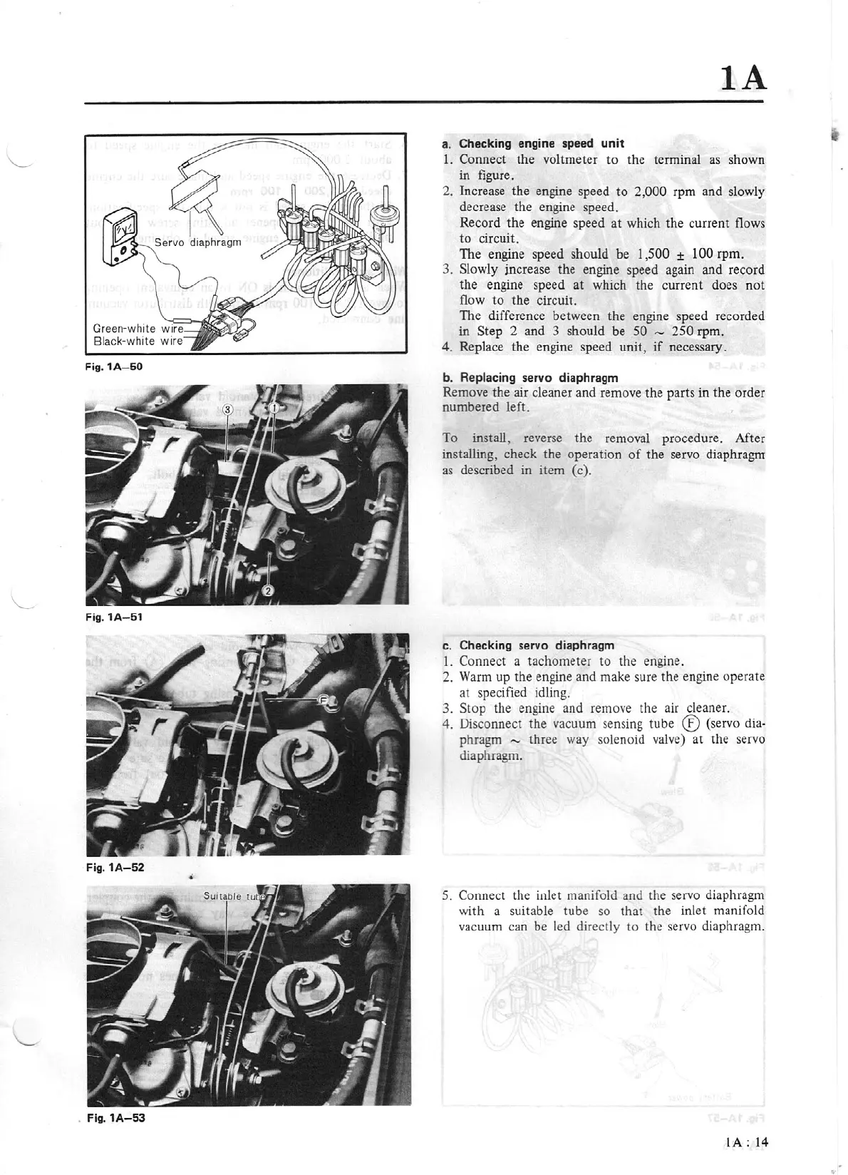
Fig.1A-50
Fig.
1A-51
Fig.
1A-52
. Fig.
1A-53
IA
a. Checking engine
speed
unit
1. Connect
the
voltmeter to the terminal
as
shown
in
figure.
2. Increase
the
engine speed
to
2,000 rpm and slowly
decrease the engine speed.
Record the engine speed
at
which
the
current flows
to circuit.
The engine speed should be 1,500
± 100 rpm.
3.
Slowly increase the engine speed again and record
the engine speed
at
which the curre
nt
does
not
flow
to
the
circuit.
The difference between the engine speed recorded
in Step 2 and 3 should be
50
"'
250 rpm.
4. Replace the engine speed
unit
,
if
necessary.
b. Replacing
servo
diaphragm
Remove the air cleaner and remove
the
parts in
the
order
numbered left.
To
install, reverse
the
removal procedure.
Af
t
er
installing, check the operation
of
the
servo diaphragm
as
described in item (c).
c. Checking
servo
diaphragm
l.
Connect a tachometer to the engine.
2. Warm up
th
e engine and make sure the engine operate
at
specified idling.
3. Stop the engine and remove the air cleaner.
4. Disconnect
the
vacuum sensing tube ® (servo dia-
phragm
"'
three way solenoid valve) at the servo
diaphragm.
5. Connect the inlet manifold and the servo diaphragm
with a
su
itable tube so that the inlet manifold
vacu
um
can be
Jed
directly
to
the servo diaphra
gm
.
lA
: 14