Fig
. 1
-5
Fig.
1-6
Fig.
1-7
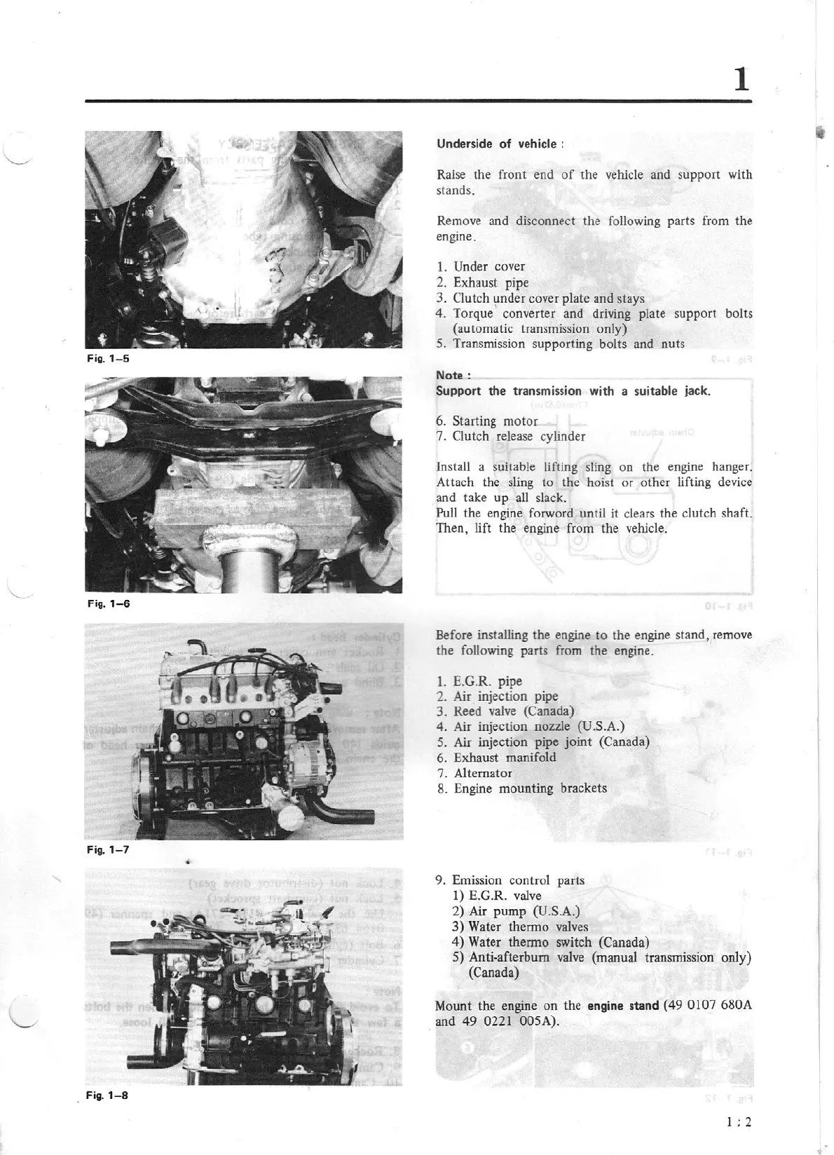
Fig.1-8
1
Underside
of
vehicle :
Raise the front end
of
the vehicle and support with
stands.
Remove and disconnect the following parts from the
engine.
1. Under cover
2. Exhaust pipe
3. Clutch
~nder
cover plate and stays
4.
Torque converter and driving plate support bolts
(automatic transmission only)
5. Transmission supporting bolts and nuts
Note:
Support the transmission with a suitable jack.
6. Starting motor
7. Clutch release cylinder
Install a suitable lifting sling on the engine hanger.
Attach the sling to the hoist or other lifting device
and take up
all
slack.
Pull the engine forword until it clears the clutch shaft.
Then, lift the engine from the vehicle.
Before installing the engine to the engine stand, remove
the following parts from the engine.
1.
E.G.R. pipe
2. Air injection pipe
3. Reed valve (Canada)
4.
Air
injection nozzle (U.S.A.)
5. Air injection pipe joint (Canada)
6. Exhaust manifold
7. Alternator
8. Engine mounting brackets
9. Emission control parts
1) E.G.R. valve
2)
Air pump (U.S.A.)
3)
Water
thenno
valves
4)
Water thermo switch (Canada)
5)
Anti-afterbum valve (manual transmission only)
(Canada)
Mount the engine on the
engine stand (49 0107 680A
and
49
0221 005A).
1 ; 2