Fig.
15-28
<D
Fig.
15-29
l
l
Fig.
15
-30
-
. .
.......
15
3.
Cowl grille attaching screws
and
fasteners
4.
Disconnect
the
washer hoses from the washer nozzle.
5.
Cowl grille
6.
Wire coupler (disconnect)
7.
Wiper
motor
and link
assembly
Note:
Ti
ghten the
bolts
attaching the wiper motor
assembly
in numerical
order
as
shown in
Fi
g.
15-29
.
To install, reverse the removal procedure.
Note:
Install
the
wiper blades
after
installing
the
wiper
moto
r
ve
rifying
the
autostop position.
T
ig
htening
torque:
Wiper arm
assembly lock
nut
1.0
-
1.2
kg·m (7 .2
-
8.7
ft-lb)
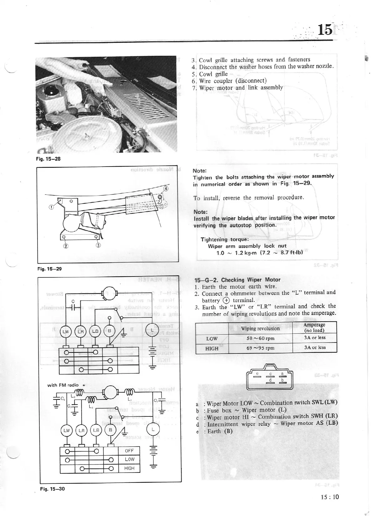
15-G
- 2. Checking Wiper Motor
1 ..
Earth
the
motor
earth wire.
2.
Connect a ohmmeter between the
" L" terminal
and
battery
© terminal.
3.
Earth the
"L
W"
or
"L
R"
terminal
and
check the
number
of
wiping revolutions
and
note
the amperage.
Wiping revolusion
Amperage
(no loa
d)
LOW
50-60
rpm 3A
or
less
HIGH
69-95
rpm 3A
or
less
a : Wiper
Mo
tor
LO
W -
Combination
switch
SWL
(LW)
b :
Fu
se
box
....,
Wiper
motor
(L)
c :
Wiper
motor
HI
-
Combinati
on
switch S
WH
(LR)
d :
Inte
rmittent wiper relay
....,
Wiper
motor
AS
(LB)
e :
Earth (B)
IS:
10