lA
Fig.
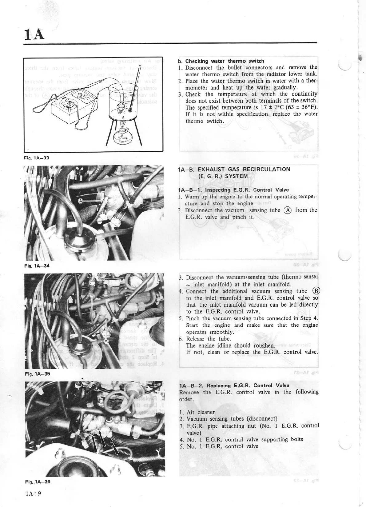
1A-33
Flg.1A-34
Fig.
1A-35
•
Fig.
1A-36
lA:
9
b. Checking water
thermo
switch
1. Disconnect the bullet connectors and remove the
water thermo switch from the radiator lower tank.
2.
Place
the water thermo switch in water with a
ther-
mometer and heat
up
the water gradually.
3. Check the temperature at which the continuity
does
not
exist between
both
terminals
of
the switch.
The specified temperature
is
17
±
2°C
(63
±
3
6°F)
.
Jf
it
is
not within specificat
ion
, replace the water
thermo switch.
1A-
B.
EXHAUST GAS RECIRCULATION
(E. G. R.)
SYSTEM
1
A-B-1.
Inspecting
E.G.R.
Control
Valve
I.
Warm
up the engine to the normal operating
temper-
ature and stop the engine.
2. Disconnect the vacuum sensing tube
@
from the
E.G.R.
valve
and pinch
it.
3. Disconnect the vacuurnssensing tube (thermo senser
-
inlet manifold)
at
the inlet manifold.
4.
Connect the additional vacuum sensing tube
@
to the inlet manifold and E.G.R. control valve so
that the inlet manifold vacuum can be led dire
ct
ly
to the E.G.R. control valve.
S.
Pinch the vacuum sensing tube connected in
St
ep
4.
Start
the engine and make sure
that
the engine
operates smoothly.
6. Release the tube.
The engine idling should roughen.
If
not
, clean
or
replace the E.G.R. co
ntr
ol valve.
1A-B-2.
Replacing
E.G
.
R.
Control Valve
Remove the E.G.R. control valve in the following
order.
I . Air cleaner
2.
Vacuum
sensing tubes (disconnect)
3. E.G.R. pipe attaching
nut
(No. 1 E.G.R. control
valve)
4.
No. I
E.G.R. control valve supporting bolts
S.
No. 1 E.G.R. control val
ve