IB
Fig.
18-1
Fi
g.
18
- 2
Fig. 1
8-3
Fig.
18
-4
IB : 1
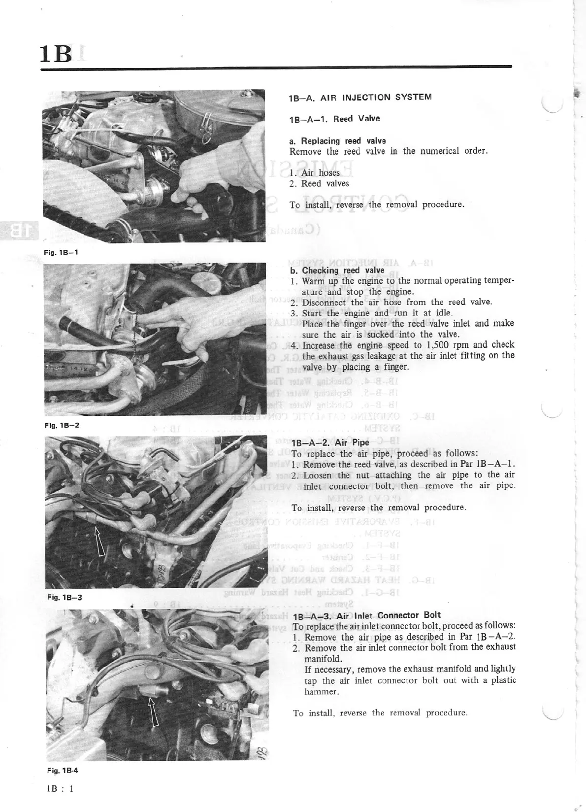
1B- A.
A
IR
INJECTION SYSTEM
18
-
A-1
. Reed Valve
a. Replacing
reed valve
Remove the reed valve in the numerical order.
J.
Air
hoses
2. Reed valves
To install, reverse the removal procedure.
b. Checking reed valve
I.
Warm up the engine to the normal operating temper·
ature and stop the engine.
2. Disconnect the air hose from the reed valve.
3. Start the engine and run it at idle.
Place
the
finger over the reed
valve
inlet and make
sure the air
is
sucked
into
the valve.
4. Increase the engine speed
to
1
,5
00
rpm and check
the
exhaust gas leakage at the air inlet fitting on the
valve
by
placing a finger.
1
B-A-2.
Air Pipe
To replace the air pipe,
proceed
as follows:
l.
Remove the reed valve, as described in
Par
lB-A
- 1.
2. Loosen the nut attaching the air pipe to the
ai
r
inlet connector bolt, then remove the air pipe.
To install, reverse the removal procedure.
18
-
A-3.
Air
Inl
et
Connector Bolt
To
replace the air inlet connector bolt, proceed as follows:
I.
Remove the air pipe as described in
Par
lB-A
-2
.
2.
Remove the air inlet connector boll from the exhaust
manifold.
If
necessary, remove the exhaust manifold and lightly
tap the air inlet
co
nnector bolt out with a plastic
hammer.
To install, reverse the removal procedure.