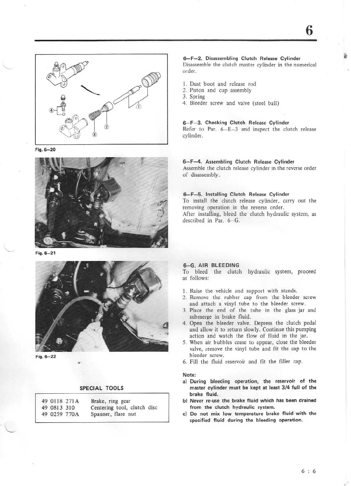
Fig. 6-
20
Fig.
6-2
1
Fig. 6-
22
•
49
011
8
271
A
49
0813
310
49
0259 770A
SPECIAL TOOLS
Brake, ring gear
Centering tool, clutch
di
sc
Spanner, flare
nu
t
6
6-F-2.
Disassembling Clutch Release Cylinder
Disassemble the clutch master cylinder in
the
numerical
order.
I. Dust b
oot
and release rod
2. Piston and cup assembly
3.
Sp
ring
4. Bleeder screw and valve (steel ball)
6-F
- 3. Checking
Clutch
Release
Cylinde
r
Refer
lo
Par.
6-
E
-3
and inspect
the
cl
u
tch
release
cylinder.
6-F-4
. Assembling Clutch Release Cylinder
Assemble
the
clutch release cylinder in the reverse order
of
disassembly.
6-F-5.
Installing
Clutch
Release Cylinder
To install the clutch release cylinder, carry
out
the
removing operation in the reverse orde
r.
After installing, bleed the clutch hydraulic system,
as
described in Par. 6-
G.
6- G. AIR BLEEDING
To bl
ee
d the clutch hydraulic system, proceed
as
fo
llows:
I.
Raise
the
vehicle and support w
ith
stands.
2. Remove
the
rubber cap from the b
le
eder screw
and attach a vinyl tube
to
the
bleeder screw.
3.
Place the end
of
the
tube in the gl
as
s jar and
submerge
in
brake fluid.
4.
Open the bleeder valve. Depress the
cl
utch pedal
and allow it to return slowly. C
ont
inue this
pu
mping
acti
on
and watch the flow
of
flu
id in
the jar.
5.
Wh
en air
bu
bbles cease to appear, close the bleeder
va
lve, remove the vinyl tube and fit
the
cap to the
bleeder screw.
6. Fill
th
e fluid reservoir and fit
the
filler cap .
Note:
al
During bleeding
operation,
the
reservoir
of
the
master
cylinder
must
be
kept
at
least
3/4
full
of
the
brake
fluid.
bl
Never re-use
the
brake
fluid
which has
been
drained
from
the
clutch
hydraulic
system
.
cl
Do
not
mix
low
temperature
brake
fluid
with
the
specified fluid
dur
ing
the
bleeding
operation.
6 6