Fig.
78
- 41
Fig.
78-42
-
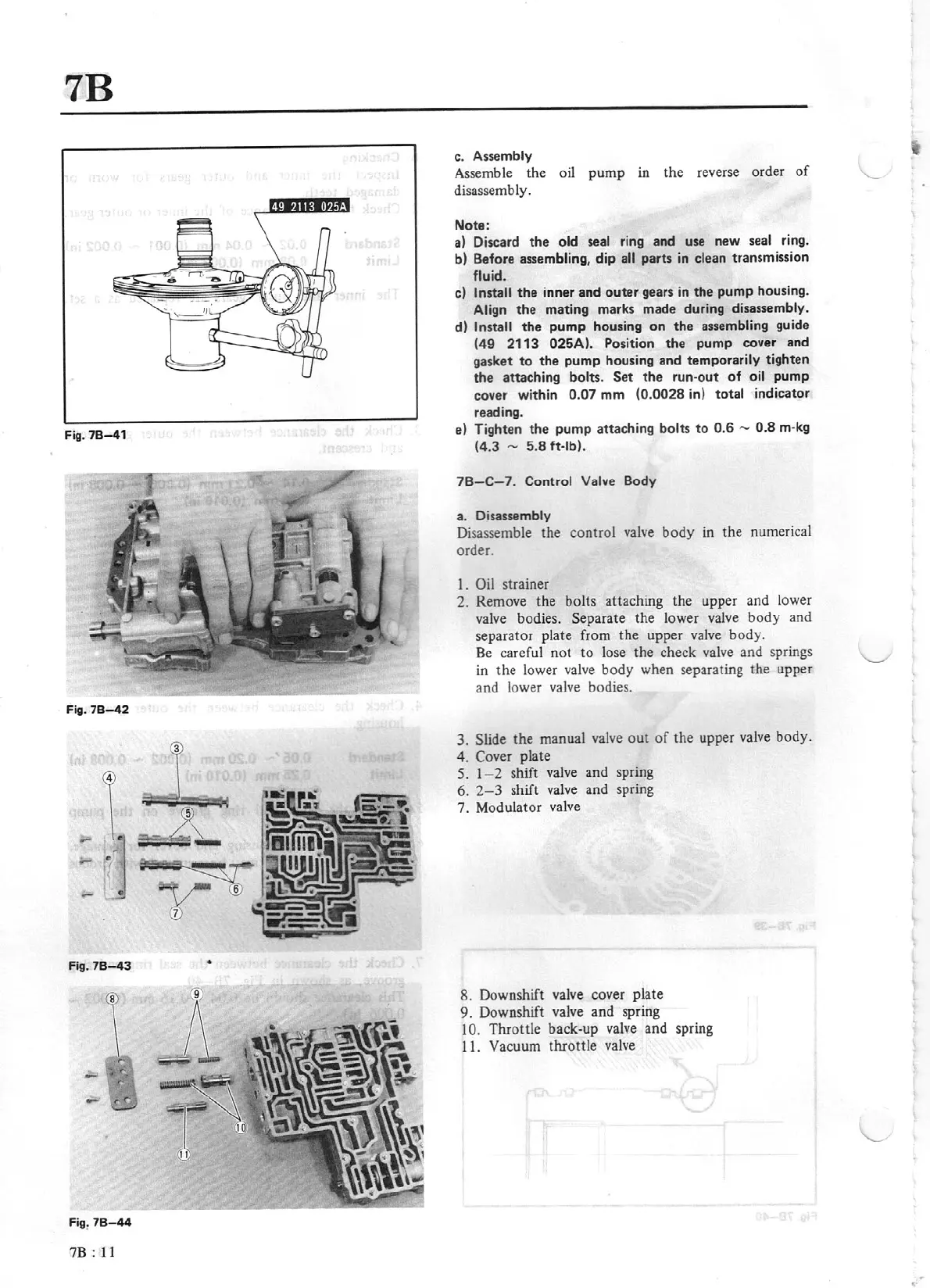
Fig. 78
-43
•
fig.
78
-
44
7B :
11
c. Assembly
Assemble
the
oil
pump
in
the
reverse order
of
disassemb
Jy
.
Note:
a)
Discard
the
old seal ring and use new
seal
ring.
b) Before assembling,
dip
all
parts
in
clean transmission
fluid.
c) Install
the
inner
and
outer
gears
in
the
pump
housing.
Align
the
mating marks made during disassembly.
d)
Install
the
pump
housing
on
the
assembling guide
(49
2113
025A). Position the
pump
cover and
gasket
to
the
pump
housing and temporarily tighten
th
e attaching bolts.
Set
the
run-out
of
oil pump
cover within
0.07
mm
(0.0028
in) total
indicator
reading.
e) Tighten the
pump
attaching
bolts
to
0.6
-
0.8
m-
kg
(4.3
-
5.8
ft-lb).
78-C-7
.
Control Valve
Body
a.
Disassembly
Disassemble the control
valve
body
in
the numerical
order
I.
Oil
strainer
2. Remove the bolts
atta
ching the upper and lower
valve
bodies.
Separate
the
lower va
lv
e
body
and
separator plate from the upper valve body.
Be
careful not
to
lose the check valve and springs
in
the
lower valve
body
when separating
the
upper
and lower valve bodies.
3.
Slide
the
manual valve
out
of
the upper valve body.
4.
Cover
plate
5.
1- 2
shift valve and spring
6.
2-3
shift valve
and
spring
7. M
odulator
valve
8. Downshift valve cover
pl
ate
9. Downshift valve
and
spring
10.
Throttle back-
up
v
al
ve
and
spring
11.
Vacuum
throttle
valve