9
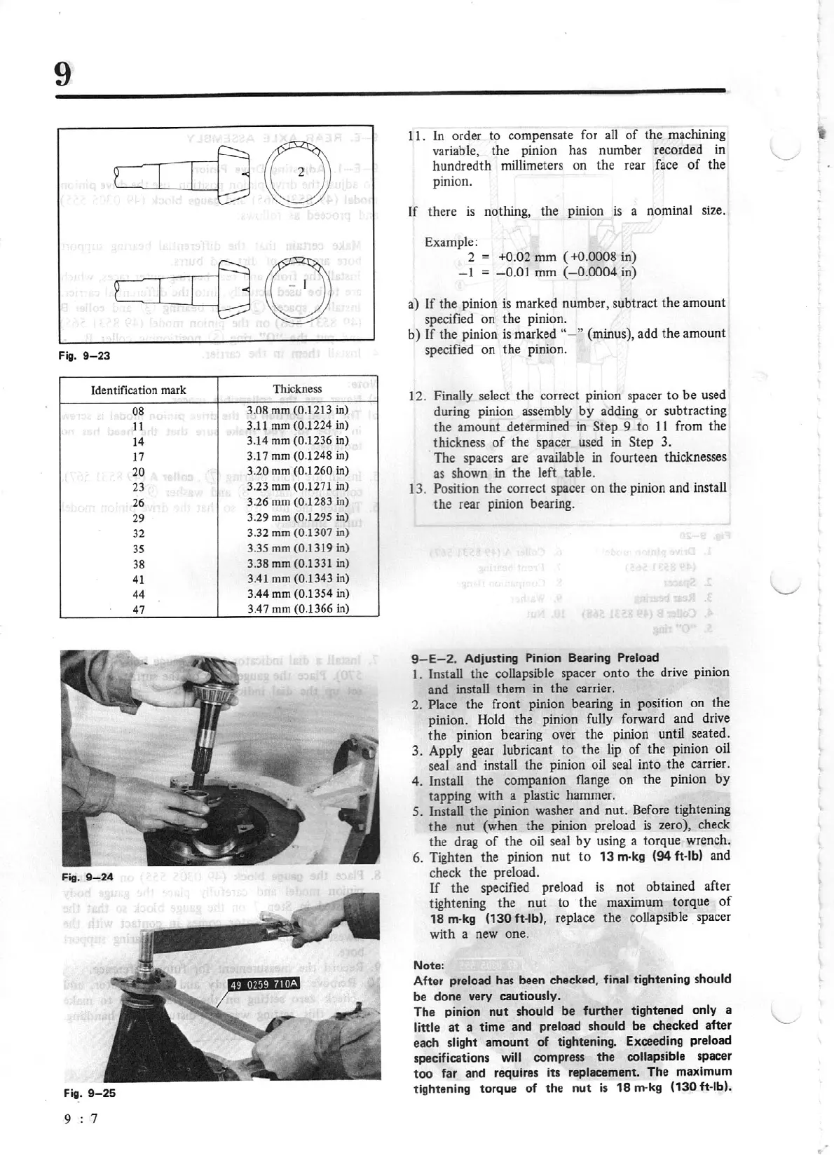
Fig.
9-23
Identification mark
Thickness
08
3.08
mm
(0.1213
in)
11
3.11
mm
(0.1224
in)
14
3.14 mm (0.1236
in)
17
3.17 mm
(0.12
48
in)
20
3.20
mm
(0.J 260
in)
23 3.23 mm (0.
12
71
in)
26 3.26 mm (0.1283
in)
29 3.29
mm
(0.1295
in)
32 3.32
mm
(0.1307
in)
35
3.
35
mm
(0.1319
in)
38 3.38 mm
(0.1331
in)
41
3.41 mm
(0.13
43
in)
44
3.
44
mm
(0.1354
in
)
47
3.
47
mm
(0
.1366
in)
Fig.
9-26
9 : 7
1
1.
In order to compensate
fo
r all
of
the machining
variable, the pinion has number recorded in
hundredth millimeters on the rear face
of
the
pinion.
If
there
is
nothing,
th
e pinion
is
a nominal size.
Example:
2 +0.02
mm
(
+0.0008
in)
- I
=
-
0.01
mm
(
-0.
0004
in)
a)
If
the pinion
is
marked number, subtract the amount
specified on the pinion.
b) If the pinion
is
marked "- "
(minus), add the amount
specified on the pinion.
12. Finally select the correct pinion spacer to
be
used
during pinion assembly
by
adding or subtracting
the amount determined in Step 9
to
11
from the
thickness
of
the spacer used in Step 3.
The spacers are available in fourteen thicknesses
as shown in the left table.
13. Position the correct spacer on the pinion and insta
ll
the rear pinion bearing.
9-
E-2
. Adjusting Pinion Bearing Preload
I.
Install the collapsible spacer
onto
the drive pinion
and install them in the carrier.
2.
Place
the front pinion bearing in position on the
pinion. Hold the pinion fully forward and drive
the
pinion bearing over the pinion until seated.
3. Apply gear lubricant
to
the lip
of
the pinion oil
seal and install the pinion oil seal into the carrier.
4. Install the companion flange on t
he
pinion
by
tapping with a plastic hammer.
5. Install the pinion washer a
nd
nut
. Before tightening
the
nut
(when the pinion preload
is
zero), check
the drag
of
the oil seal
by
using a
to
rque wrench.
6. Tighten the pinion
nut
to
13
m-kg
(94
ft-lb) and
check the preload.
If
the specified preload
is
not
obt
ained after
tightening the nut
to
the maximum torque
of
18
m-kg
(130
ft
-lb),
replace
the
collapsible spacer
with a new one.
Note:
After preload has been checked,
final
tightening should
be done very cautiously.
The pinion
nu
t should
be
further tightened
only
a
little
at a time
and
preload
should
be
checked after
each
slig
ht
amount
of
tighteni
ng.
Exceeding preload
specifications
will
compress
the
collapsible
spacer
too
far and requires
its
replacement. The maximum
tightening torque
of
the nut
is
18
m-kg
(130
ft-lb).