Fig.
15-2
,_
Fig.
15-3
=
u,*.,
0
>.'._-'
{(I})
• '
r:f..
I
.
..
\
..
\HU
IUllfUf
0'~
\fUP
l
JUfl
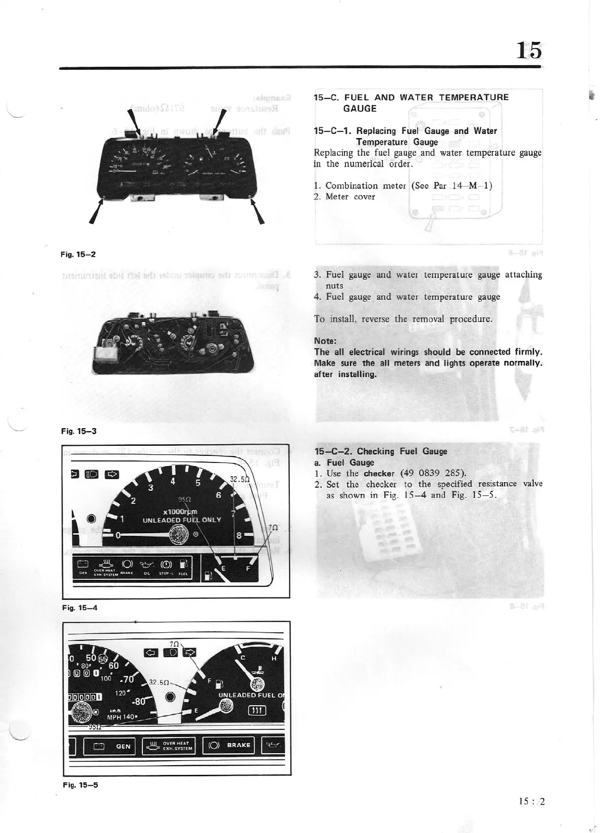
Fig.
15-4
Fig.
15-5
15-C.
FUEL
AND WATER
TEMPERATURE
GAUGE
15-C-1.
Replacing Fuel Gauge and Water
Temperature Gauge
15
Replacing the fuel gauge and water temperature gau
ge
in the numerical order.
1.
Combination meter
(See Par
14-M
-
l)
2.
Meter cover
3. Fuel gauge and water temperature gauge attaching
nuts
4. Fuel gauge and water temperature gauge
To
install, reverse the removal procedure.
Note:
The
all electrical
wmngs
should
be
connec
ted firmly.
Make sure
the all
meters and lights
operate
normally.
after
installing.
15-C
-2
. Checking Fuel Gauge
a. Fuel Gauge
1.
Use the
checker
(49 0839
285).
2.
Set the checker to the specified resistance
valve
as shown
in
Fig.
15-4
and Fig.
15-5.
15:
2