5
Fig.
5-14
Fig.
5-15
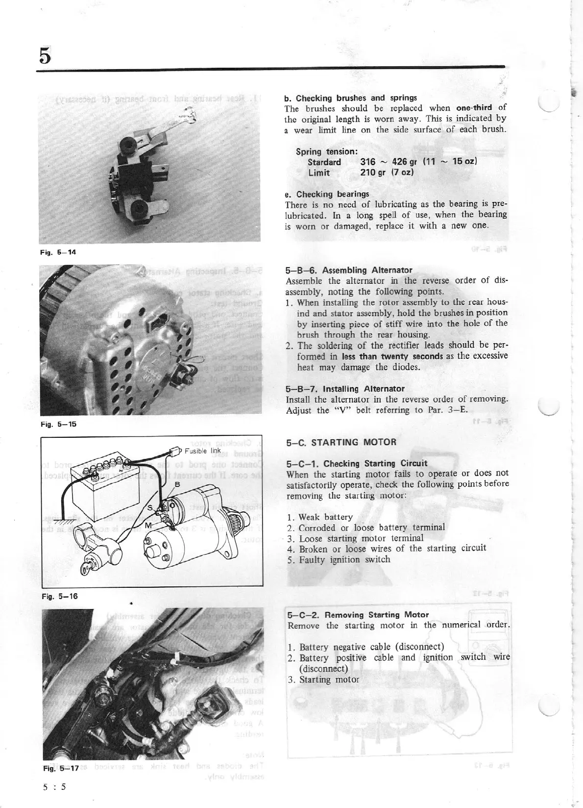
Fig.
5-16
•
Fig. 5-
17
s : s
b. Checking
brushes and springs
The brushes should be replaced when one-third
of
the original length
is
worn away. This
is
indicated
by
a wear limit line on the side surface
of
each brush.
Spring
tension:
Stardard
316
- 426 gr
(11
- 15 oz)
Limit
210 gr (7 oz)
e.
Checking
bearings
There
is
no need
of
lubricating as the bearing
is
pre-
lubricated.
In
a long spell
of
use, when the bearing
is
worn
or
damaged, replace
it
with a new one.
5-B-6.
Assembling Alternator
Assemble the alternator in the reverse order
of
dis-
assembly, noting the following points.
I.
When
installing the rotor assembly to the rear hous-
ind and stator
assembly, hold the brushes in position
by inserting piece
of
stiff wire into the hole
of
the
brush through the rear housing.
2. The soldering
of
the rectifier leads should be
per-
formed in
less
than twenty seconds as the excessive
heat may damage the diodes.
5-B
- 7.
Installing Alternator
Install the alternator in the reverse order
of
removing.
Adjust the
"V"
belt referring
to
Par.
3-
E.
5-C
. STARTING
MOTOR
5-C-1
. Checking
Starting
Circuit
When the starting motor fails
to
operate
or
does not
satisfactorily operate, check the following points before
removing the starting motor:
I.
Weak
battery
2.
Corroded or loose battery terminal
3. Loose starting motor terminal
4. Broken
or
loose wires
of
the starting circuit
S. Faulty ignition switch
5-C-2.
Removing Starting Motor
Remove the starting motor in the numerical order.
I.
Battery negative cable (disconnect)
2. Battery positive cable and ignition switch wire
(disconnect)
3. Starting motor