1
Fig. 1-
81
Fig. 1-
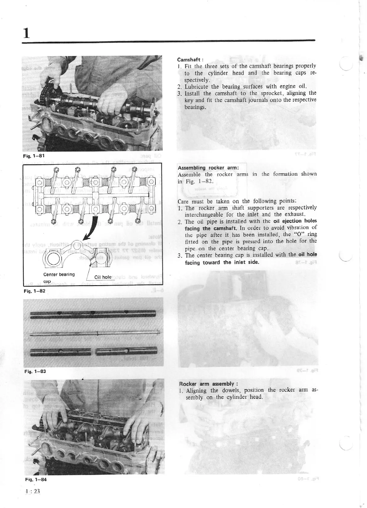
82
e:·
·---·
--
Fig.
1-83
Fig. 1
-8
4
1 :
23
Camsha
ft:
I.
Fit the three sets
of
the camshaft bearings properly
to
the
cylinder head and the bearing caps
re-
spectively.
2.
Lubricate the bearing surfaces with engi
ne
oil.
3.
Install the camshaft
to
the s
pr
ocket, aligning the
key and
fit the
camshaft journals
onto
the
respective
bearings.
Assembling rocker arm:
Assemble the rocker arms in the formation shown
in
Fig.
1-82.
Care must be taken
on
the following points:
I.
The
rocker arm shaft supporters are respectively
interchangeable for the inlet and the exhaust.
2. The o
il
pipe is installed with the oil ejection holes
facing
the
camshaft.
In
order
to
avoid vibration
of
the pipe after it has been installed, the
"O"
ring
fitted
on
the pipe
is
pressed
into
the hole for the
pipe
on
the
center
bearing cap.
3.
The
center bearing cap
is
installed with the
oil hole
facing toward the inlet
side.
Rocker arm assembly :
I.
Aligning the dowels, position the rocker arm
as
-
sembly
on
the cylinder head.