lA
Fig.
1A-10
Fig.
1A-11
•
Fig.
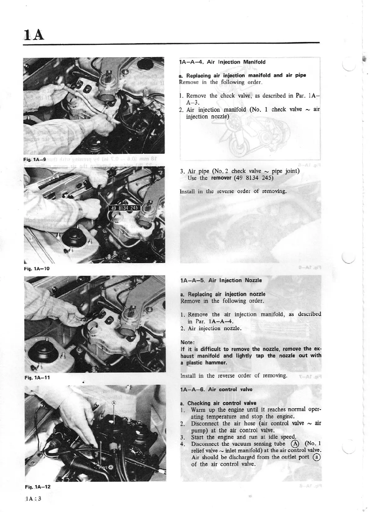
1A-12
lA:
3
1
A-A-4.
Air Injection Manifold
a. Replacing air
injection manifold
and air pipe
Rem
ove
in the following order.
l.
Remo
ve
the check
valve,
as described in
Par.
lA
-
A- 3.
2.
Air injection manifold (No.
l
check
valve
,....,
air
injection nozzle)
3.
Air
pipe (No.
2
check
valve
-
pipe
joint)
Use
the
remover (49 8134 245)
Install in the reverse order
of
removing.
1A-A-5.
Air Injection
Nozzle
a. Replacing air injection
nozzle
Remove in the following order.
l.
Remove the air injection manifold, as described
in Par.
I
A-A-4.
2.
Air
injection nozzle.
Note:
If
it
is
difficult
to
remove the nozzle, remove the
ex·
haust manifold and
lightly
tap the nozzle
out
with
a
lastic
hammer.
Install in the reverse order
of
removing.
1A-A-6.
Air control
valve
a. Checking air control
valve
I .
Warm
up the engine until
it
reaches normal oper-
ating temperature and stop the engine.
2. Disconnect the air hose (air control
valve
- air
pump) at the
air
control valve.
3.
Start
the engine and run at idle speed.
4.
Disconnect the vacuum sensing tube
@
(No.
1
relief
valve
- inlet manifold) at the air control
valve
.
Air should
be
discharged from the outlet port
@
of
the
air
control valve.