3
Fig.
3-8
Fig
.3-
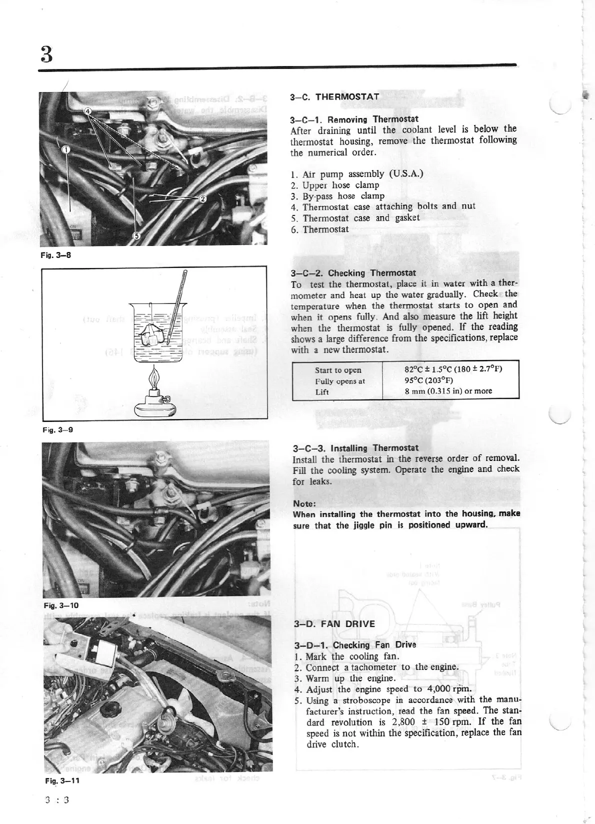
9
Fig.
3-10
Fig.
3-11
3 : 3
3
-C.
THERMOSTAT
3
-C-
1.
Remo
vi
ng Thermostat
After
draining until the coolant
level
is
below the
thermostat housing, remove the thermostat following
the numerical order.
I.
Air
pump assembly (U.S.A.)
2.
Upper
hose clamp
3. By-pass hose clamp
4.
Thermostat case
attaching
bolts and
nut
5. Thermostat case and gasket
6. Thermostat
3-C-2.
Checking Thermostat
To test the thermostat, place it in water with a ther-
mometer and heat up the water gradually. Check the
temperature when the thermostat starts to open and
when it opens fully. And also measure
the
lift
height
when the thermostat is fully opened.
If
the reading
shows a large difference from the specifications, replace
with a new thermostat.
Swt
to
ope
n
Fully opens
at
Lift
82°C
±
1.5°C {180
± 2.7°F)
95°C (203°F)
8
mm
(0.315
in)
or
more
3-C-3.
Installing Thermostat
Install the thermostat in
the
reverse
order
of
removal.
Fill the cooling system. Operate the
engine
and check
for leaks.
Note:
When
installing
the
thermostat
in
to
th
e housing,
make
sure
that
the
jiggle pin
is
positioned upward.
3-0
.
FA
N DRIVE
3-D-1.
Checking Fan Drive
I.
Mark the cooling fan.
2. Connect a tachometer
to
the engine.
3.
Warm
up the engine.
4. Adjust the
engine
speed
to
4,
000
rpin.
5.
Using
a stroboscope in accordance with the
manu-
facturer's instruction, read the fan speed. The stan-
dard revolution
is
2,800
±
150
rpm.
If
the fan
speed
is
not
within the specification, replace the fan
drive clutch.