9
Fig.
9-30
Fig.
9-31
'
~
Fig.
9-32
Fig.
9-33
9 : 9
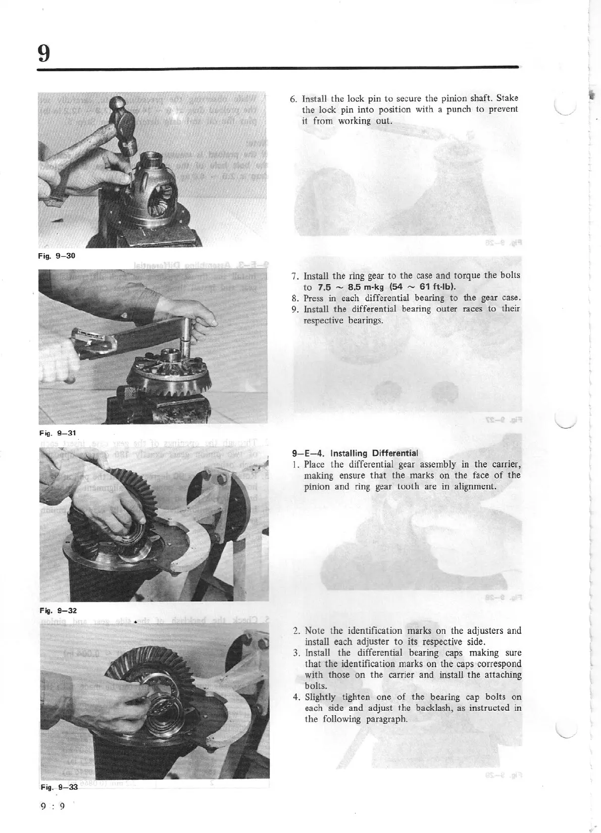
6. Install the lock pin to secure the pinion shaft.
Stake
the lock pin into position
wi
th a punch
to
prevent
it from working out.
7.
Install the ring gear
to
the case and torque the bolts
to
7.5
-
8.5 m-kg (54
-
61
ft-lb).
8. Press
in
each differential bearing
to
the gear case.
9. Install the differential bearing outer races to their
respective bearings.
9-
E-4.
Installing Differential
I.
Place the differential gear assembly in the carrier,
making ensure
that
the marks
on
the face
of
the
pinion and ring gear tooth are
in
alignment.
2. Note the identification marks
on
the adj usters and
install each adjuster
to
its respective side.
3. Install the differential bearing caps making sure
that
the identification marks on the caps correspond
with those on the carrier and install the attaching
bolts.
4.
Slightly
tighten one
of
the bearing cap bolts
on
each side and adjust the backlash, as instructed
in
the following paragraph.