Basic operation procedure (External operation)
BASIC OPERATION
117
4
4.6.5 Using an analog signal (current input) to give a
frequency command
POINTPOINT
• Switch ON the STF (STR) signal to give a start command.
• Turn ON the AU signal.
•Set Pr.79 Operation mode selection="2" (External operation mode).
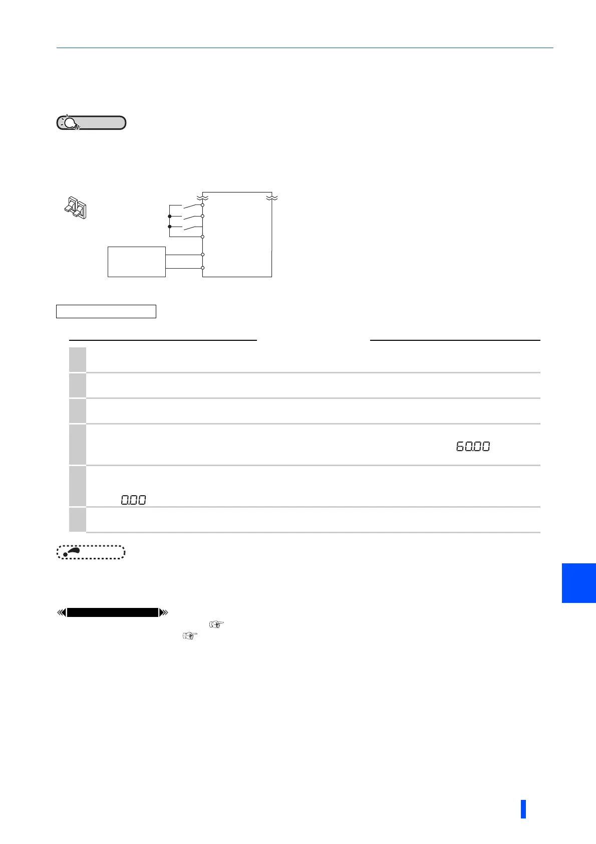
[Connection diagram]
NOTE
• When both the forward rotation switch (STF) and the reverse rotation switch (STR) are ON, the motor cannot be started. If
both are turned ON while the inverter is running, the inverter decelerates to a stop.
• Pr.184 AU terminal function selection must be set to "4" (AU signal) (initial value).
Pr.7 Acceleration time, Pr.8 Deceleration time page 285
Pr.184 AU terminal function selection page 430
Operation example Operate at 60 Hz.
Operation
1.
Screen at power-ON
The monitor display appears.
2.
Terminal 4 input selection
Turn ON the terminal 4 input selection signal (AU). Input to the terminal 4 is enabled.
3.
Start
Turn ON the start switch (STF or STR). [FWD] or [REV] flickers as no frequency command is given.
4.
Acceleration constant speed
Input 20 mA.The frequency value on the indication increases in Pr.7 Acceleration time, and " " (60.00 Hz)
appears. [FWD] indicator is on during the forward rotation, and [REV] indicator is on during the reverse rotation.
5.
Deceleration
Input 4 mA or less.The frequency value on the indication decreases in Pr.8 Deceleration time, and the motor stops rotating
with " " (0.00 Hz) displayed. [FWD] or [REV] indicator flickers.
6.
Stop
Turn OFF the start switch (STF or STR). [FWD] or [REV] indicator turns OFF.
Inverter
Switch
5(-)
4(+)
Forward rotation start
Reverse rotation start
STF
STR
SD
AU
Current signal
source
(4 to 20mADC)

 Loading...


