(M) Monitor display and monitor output signal
398
PARAMETERS
5.11.10 Remote output function
Remote output setting (REM signal, Pr.496, Pr.497)
Remote output data retention (REM signal, Pr.495)
The inverter output signals can be turned ON/OFF like the remote output terminals of a programmable controller.
Pr. Name
Initial
value
Setting
range
Description
495
M500
Remote output
selection
0
0
Remote output data is cleared when
the power supply is turned OFF
Remote output data is
cleared during an inverter
reset
1
Remote output data is retained when
the power supply is turned OFF
10
Remote output data is cleared when
the power supply is turned OFF
Remote output data is
retained during an inverter
reset
11
Remote output data is retained when
the power supply is turned OFF
496
M501
Remote output data 1
0 0 to 4095
Set values for the bits corresponding to each output terminal of the
inverter output terminal. (Refer to the diagram below.)
497
M502
Remote output data 2
0 0 to 4095
Set values for the bits corresponding to each output terminal of
options FR-A8AY and FR-A8AR. (Refer to the diagram below.)
Pr.496
Pr.497
Any value.
Y0 to Y6 are available when the extension output option
(FR-A8AY) is installed.
RA1 to RA3 are available hen the relay output option
(FR-A8AR) is installed.
• The output terminal can be turned ON/OFF with the Pr.496
and Pr.497 settings. ON/OFF control can be performed for
the remote output terminal via the PU connector, RS-485
terminals and communication option.
• To assign the Remote output (REM) signal to the terminal to
be used for remote output, set "96 (positive logic) or 196
(negative logic)" in any of Pr.190 to Pr.196 (output terminal
function selection).
• Refer to the left figure, and set "1" in the terminal bit
(terminal with the REM signal assigned) of Pr.496 or Pr.497
to turn ON the output terminal (OFF when using negative
logic). Set "0" to turn OFF the output terminal (ON when
using negative logic).
• For example, when Pr.190 RUN terminal function
selection = "96" (positive logic) and "1" (H01) is set in
Pr.496, the terminal RUN turns ON.
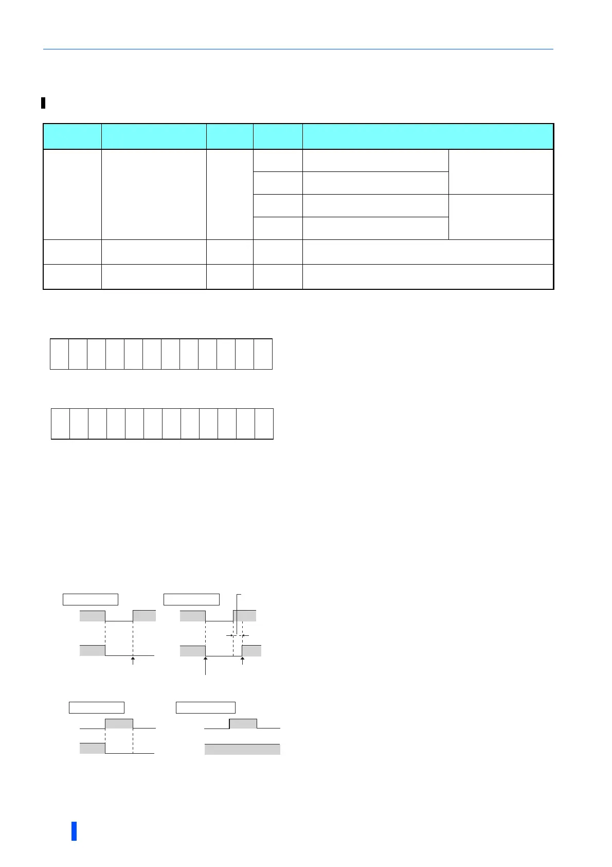
• If the power supply is reset (including a power failure) while
Pr.495 = "0 (initial value) or 10", t the REM signal output is
cleared. (The terminal ON/OFF status is determined by the
settings in Pr.190 to Pr.196.) "0" is also set in Pr.496 and
Pr.497.
• When Pr.495 = "1 or 11", the remote output data is saved in
EEPROM before the power supply is turned OFF. This
means that the signal output after power restoration is the
same as before the power supply was turned OFF.
However, when Pr.495 = "1", the data is not saved during
an inverter reset (terminal reset, reset request via
communication).
• When Pr.495 = "10 or 11", the signal before the reset is
saved even during an inverter reset.
b11 b0
ABC1
ABC2
∗1
∗1
∗1
∗1
∗1
FU
OL
IPF
SU
RUN
b11 b0
Y5 ∗2
Y6 ∗2
RA1 ∗3
RA2 ∗3
RA3 ∗3
∗1
∗1
Y4 ∗2
Y3 ∗2
Y2 ∗2
Y1 ∗2
Y0 ∗2
Power
supply
OFF OFF
ONOFF
Power
supply
REMREM
REM signal clear REM signal held
Inverter
reset time
(about 1s)
Pr.495 = 0, 10 Pr.495 = 1, 11
ON/OFF example for positive logic
Signal condition during a reset
Reset
ON
ON
OFF
REM
∗
Reset
ON
ON
REM
Pr.495 = 0, 1
Pr.495 = 10, 11
∗ When Pr.495 = "1", the signal condition saved in EEPROM
(condition of the last power OFF) is applied.
REM signal is saved

 Loading...


