Measurement of main circuit voltages, currents and powers
PRECAUTIONS FOR MAINTENANCE AND INSPECTION
687
7
7.2.7 Measurement of inverter output frequency
In the initial setting of the FM-type inverter, a pulse train proportional to the output frequency is output across the pulse train
output terminals FM and SD of the inverter. This pulse train output can be counted by a frequency counter, or a meter
(moving-coil type voltmeter) can be used to read the mean value of the pulse train output voltage. When a meter is used to
measure the output frequency, approximately 5 VDC is indicated at the maximum frequency.
For detailed specifications of the pulse train output terminal FM, refer to page 375.
In the initial setting of the CA-type inverter, a pulse train proportional to the output frequency is output across the analog
current output terminals CA and 5 of the inverter. Measure the current using an ammeter or tester.
For detailed specifications of the analog current output terminal CA, refer to page 377.
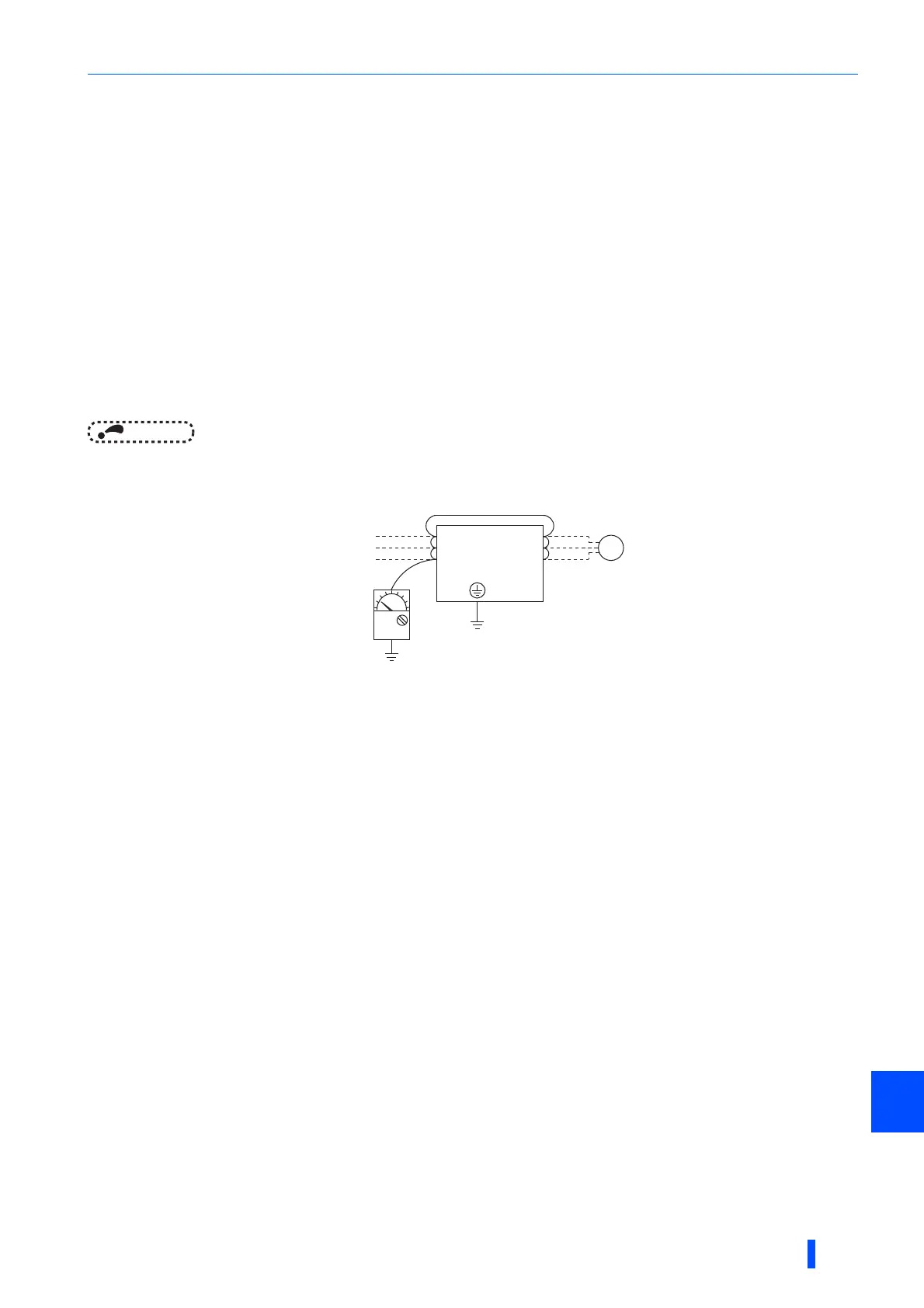
7.2.8 Insulation resistance test using megger
• For the inverter, conduct the insulation resistance test on the main circuit only as shown below and do not perform the test
on the control circuit. (Use a 500 VDC megger.)
NOTE
• Before performing the insulation resistance test on the external circuit, disconnect the cables from all terminals of the inverter
so that the test voltage is not applied to the inverter.
• For the continuity test of the control circuit, use a tester (high resistance range) and do not use the megger or buzzer.
7.2.9 Pressure test
Do not conduct a pressure test. Deterioration may occur.
U
V
W
Inverter
500VDC
megger
Power
supply
IM
Motor
R/L1
S/L2
T/L3

 Loading...


