(A) Application parameters
PARAMETERS
547
5
GROUP
A
NOTE
• If the project data of the PLC function is locked with a password using FR Configurator 2, copying to the USB memory device
and verification are disabled. Also if set to write-disabled, writing to the inverter is disabled.For the details of the PLC function,
refer to the PLC Function Programming Manual and the Instruction Manual of FR Configurator 2.
Pr.338 Communication operation command source page 316
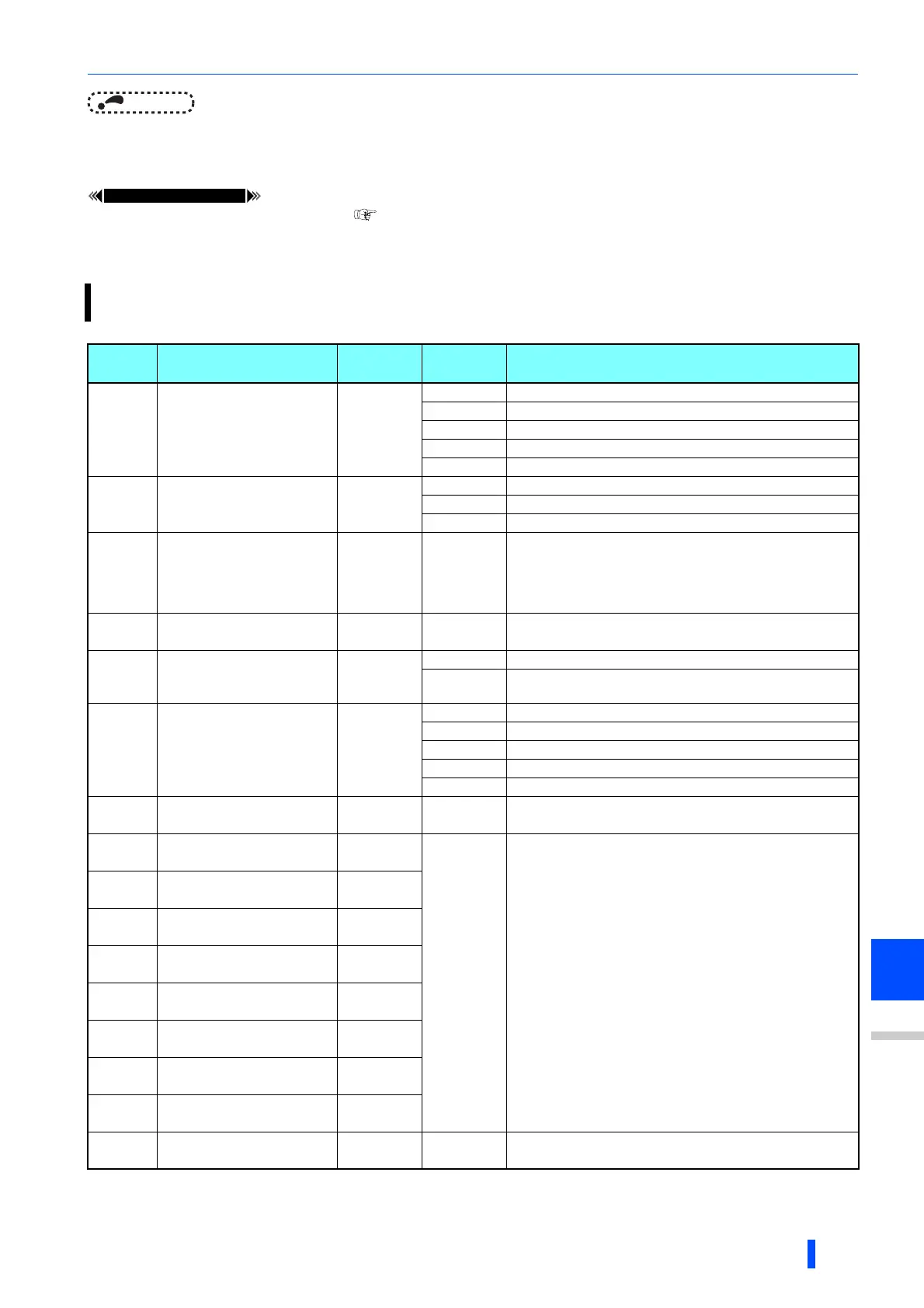
5.14.18 Trace function
• The operating status of the inverter can be traced and saved on a USB memory device.
• Saved data can be monitored by FR Configurator 2, and the status of the inverter cam be analyzed.
Pr. Name
Initial
value
Setting
range
Description
1020
A900
Trace operation selection
0
0 Without trace operation
1 Sampling start
2 Forced trigger
3 Sampling stop
4 Transfer of data to USB memory divice
1021
A901
Trace mode selection
0
0 Memory mode
1 Memory mode (automatic transfer)
2 Recorder mode
1022
A902
Sampling cycle
2 0 to 9
Set the sampling cycle.
0: 0.125 ms, 1: 0.252 ms, 2: 1 ms, 3: 2 ms,
4: 5 ms, 5: 10 ms, 6: 50 ms, 7: 100 ms, 8: 500 ms, 9: 1 s
(Regarding the setting value "0 and 1", the cycle varies by the
control mode.)
1023
A903
Number of analog
channels
4 1 to 8 Select the number of analog channels to be sampled.
1024
A904
Sampling auto start
0
0 Manual sampling start
1
Sampling starts automatically when the power supply is turned
ON or at a reset
1025
A905
Trigger mode selection
0
0 Fault trigger
1 Analog trigger
2 Digital trigger
3 Analog or digital trigger (OR logic)
4 Both analog and digital trigger (AND logic)
1026
A906
Number of sampling
before trigger
90% 0 to 100%
Set the percentage of the pre-trigger sampling time with
respect to the overall sampling time.
1027
A910
Analog source selection
(1ch)
201
1 to 3,
5 to 14,
17 to 20,
22 to 24,
32 to 35,
40 to 42,
52 to 54,
61, 62, 64,
67, 87 to 98,
201 to 213,
222 to 227,
230 to 232,
235 to 238
Select the analog data (monitor) to be sampled on each
channel.
1028
A911
Analog source selection
(2ch)
202
1029
A912
Analog source selection
(3ch)
203
A1030
A913
Analog source selection
(4ch)
204
1031
A914
Analog source selection
(5ch)
205
1032
A915
Analog source selection
(6ch)
206
1033
A916
Analog source selection
(7ch)
207
1034
A917
Analog source selection
(8ch)
208
1035
A918
Analog trigger channel
1 1 to 8 Select the analog channel to be the trigger.

 Loading...


