(T) Multi-Function Input Terminal Parameters
406
PARAMETERS
5.12.1 Analog input selection
Analog input specification selection
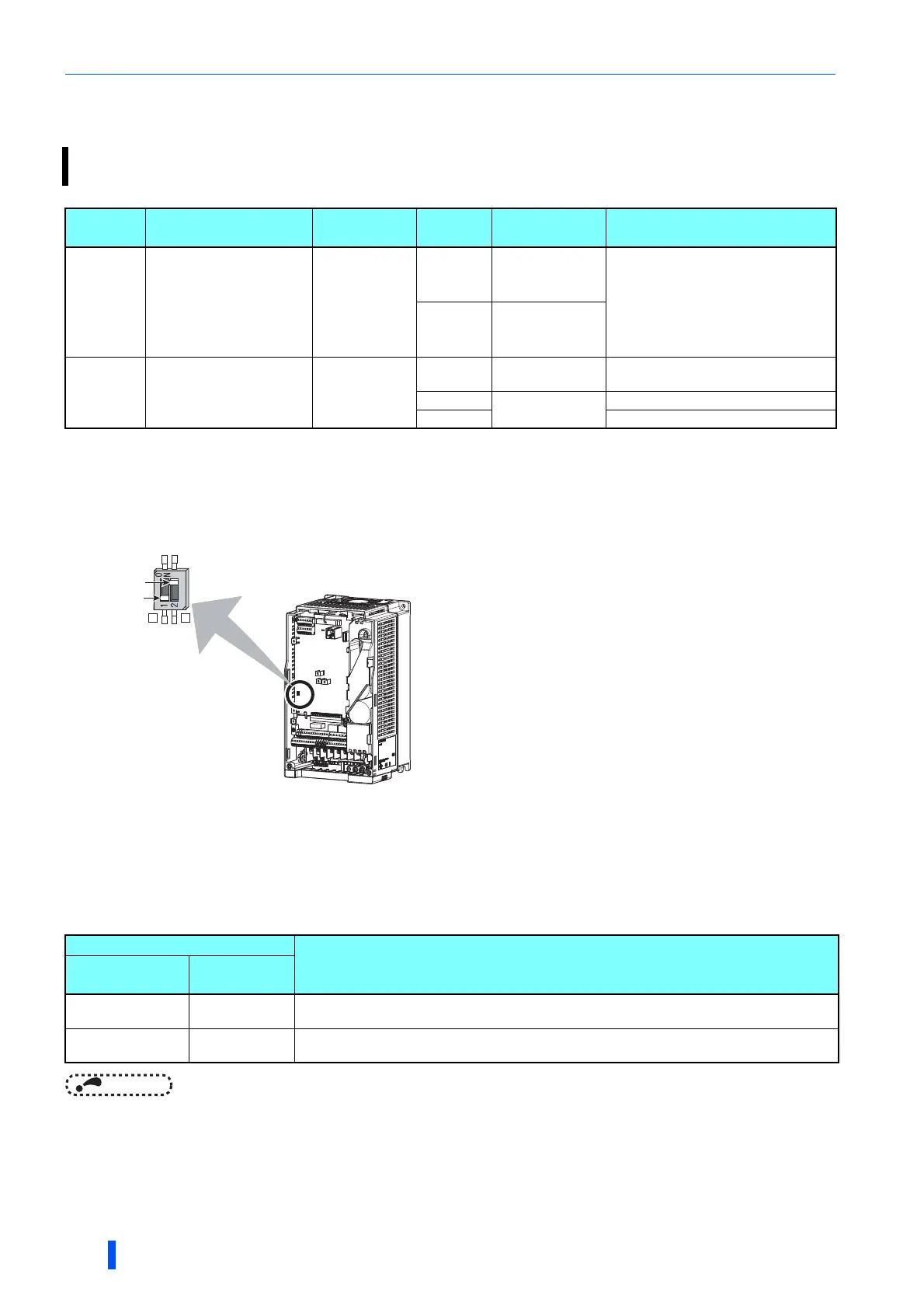
• Concerning the terminals 2 and 4 used for analog input, the voltage input (0 to 5 V, 0 to 10 V) and current input (0 to 20 mA)
are selectable. To change the input specification, change the parameters (Pr.73, Pr.267) and voltage/current input switch
settings (switches 1, 2).
• The terminal 2/4 rating specifications change depending on the voltage/current input switch settings.
Voltage input: input resistance 10 k ±1 k, permissible maximum voltage 20 VDC
Current input: input resistance 245 ±5 , permissible maximum current 30 mA
• Correctly set Pr.73, Pr.267 and voltage/current input switch settings so that the analog signal appropriate for the settings is
input. The incorrect settings shown in the table below cause a failure. Other incorrect settings result in an incorrect
operation.
NOTE
• Check the voltage/current input switch number indication before setting, because it is different from the FR-A700 series
switch number indication.
The functions to switch the analog input terminal specifications, override function, forward/reverse rotation by the input
signal polarity are selectable.
Pr. Name Initial value
Setting
range
Description
73
T000
Analog input selection
1
0 to 5, 10
to 15
Switch 1 - OFF
(initial status)
The terminal 2 input specification (0 to 5
V, 0 to 10 V, 0 to 20 mA) and terminal 1
input specification (0 to ±5 V, 0 to ±10
V) are selectable.
Also the override and reversible
operation settings are selectable.
6, 7, 16, 17 Switch 1 - ON
267
T001
Terminal 4 input
selection
0
0
Switch 2 - ON
(initial status)
Terminal 4 input, 4 to 20 mA
1
Switch 2 - OFF
Terminal 4 input, 0 to 5 V
2 Terminal 4 input, 0 to 10 V
Switch 1: Terminal 2 input
ON: Current input
OFF: Voltage input (initial status)
Switch 2: Terminal 4 input
ON: Current input (initial status)
OFF: Voltage input
Setting causing a failure
Operation
Switch setting
Terminal
input
ON (current input) Voltage input
Causes an analog signal output circuit failure in an external device
(due to increased loads on the signal output circuit of the external device).
OFF (voltage input) Current input
Causes an input circuit failure in the inverter
(due to an increased output power in the analog signal output circuit of an external device).
Voltage/current
input switch
2 4
Switch 1
Switch 2

 Loading...


