(A) Application parameters
524
PARAMETERS
NOTE
• When Pr.128 is set to "0" or the X14 signal is OFF, regular inverter running not dancer control is performed.
• Dancer control is enabled by turning ON/OFF the bits of terminals assigned the X14 signal by RS-485 communication or over
the network.
• When dancer control is selected, set the PID output suspension function (Pr.575 Output interruption detection time =
"9999")
• When Pr.561 PTC thermistor protection level "9999", terminal 2 cannot be used for the main speed command. Terminal
2 becomes the PTC thermistor input terminal.
Selection of set point/measured value input method (Pr.609, Pr.610)
• Select the set point input method by Pr.609 PID set point/deviation input selection and the measured value input method
by Pr.610 PID measured value input selection. Switch the power voltage/current specifications of terminals 2 and 4 by
Pr.73 Analog input selection or Pr.267 Terminal 4 input selection to match the specification of the input device.
• When Pr.133 PID action set point "9999", Pr.133 is the set point.
When the set point is set at Pr.133, the setting frequency of Pr.902 is equivalent to 0% and the setting frequency of Pr.903
is equivalent to 100%.
When the same input method has been selected for the set point and measured value at Pr.609 and Pr.610, set point input is invalid. (Inverter
runs at set point 0%)
NOTE
• After changing the Pr.73 and Pr.267 settings, check the voltage/current input switch. Incorrect setting may cause a fault,
failure or malfunction.(For the details of the setting, refer to page 406.)
• When terminals 2 and 4 are selected for deviation input, perform bias calibration using C3 and C6 to prevent a minus voltage
from being entered as the deviation input signal. Input of a minus voltage might damage devices and the inverter.
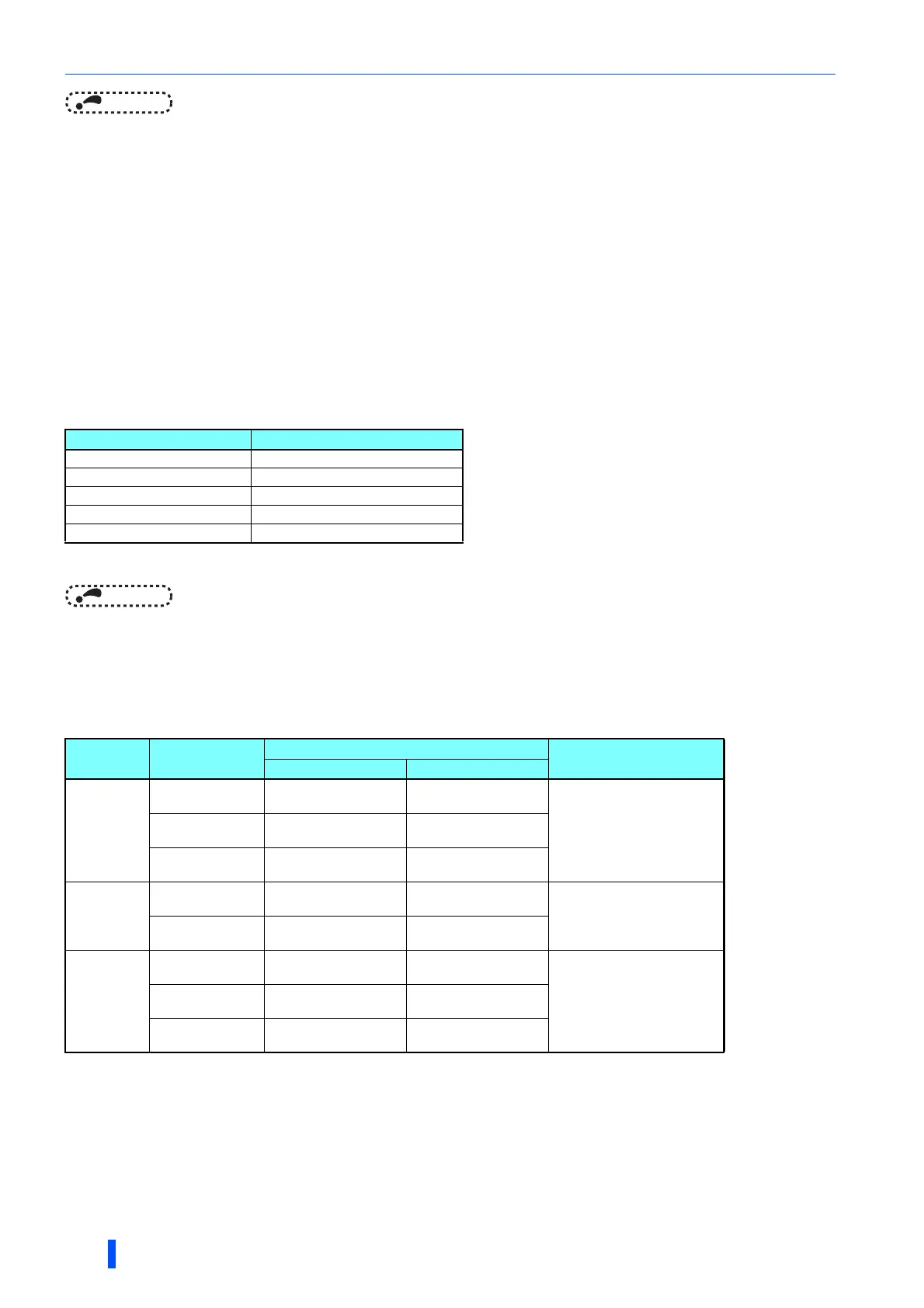
• The following shows the relationship between the input values of the analog input terminals, and the set point and
measured value.
Can be changed by Pr.73 and Pr.267 and the voltage/current input switch. (Refer to page 406.)
Pr.609, Pr.610 settings Input method
1 Terminal 1
2 Terminal 2
3 Terminal 4
4 CC-Link communication
5 PLC function
Input
terminal
Inspect
specification
Relationship with analog input
Calibration parameter
Set point Result
Terminal 2
0 to 5 V
0 V=0%
5 V=100%
0 V=0%
5 V=100%
Pr.125, C2 to C40 to 10 V
0 V=0%
10 V=100%
0 V=0%
10 V=100%
0 to 20 mA
0 mA=0%
20 mA=100%
0 mA=0%
20 mA=100%
Terminal 1
0 to 5 V
-5 V to 0 V=0%
5 V=+100%
-5 V to 0 V=0%
5 V=+100%
When Pr.128 = "10"
Pr.125, C2 to C4
When Pr.128 "1000"
C12 to C15
0 to 10V
-10 V to 0 V=0%
10 V=+100%
-10 V to 0 V=0%
10 V=+100%
Terminal 4
0 to 5 V
0 V to 1 V=0%
5 V=100%
0 V to 1 V=0%
5 V=100%
Pr.126, C5 to C70 to 10 V
0 V to 2 V=0%
10 V=100%
0 V to 2 V=0%
10 V=100%
0 to 20 mA
0 to 4 mA=0%
20 mA=100%
0 to 4 mA=0%
20 mA=100%

 Loading...


