Position control under vector control and PM sensorless vector control
244
PARAMETERS
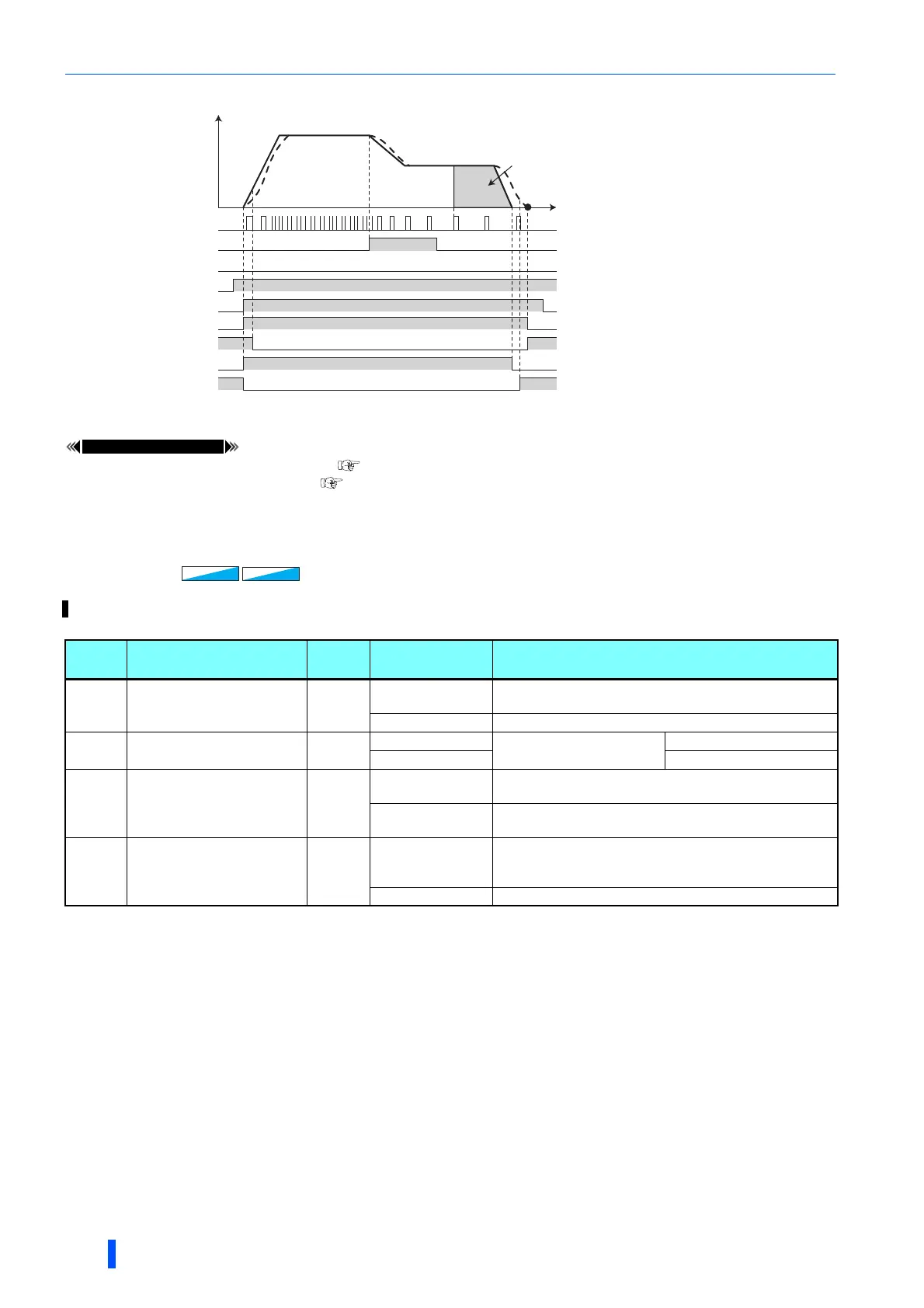
• Output signal operation during positioning with home position return
Pr.20 Acceleration/deceleration reference frequency page 285
Pr.29 Acceleration/deceleration pattern selection page 290
5.5.5 Position control by inverter pulse train input
The simple position pulse train command can be input by pulse train input and sign signal (NP) to the JOG terminal.
Pr. Name
Initial
value
Setting range Description
419
B000
Position command
source selection
0
0
Simple position control by point tables (position command by
setting parameters).
2 Simple pulse train command by inverter pulse input.
428
B009
Command pulse
selection
0
0 to 2
Pulse train + rotation
direction sign
Negative logic
3 to 5 Positive logic
429
B010
Clear signal selection
1
0
The deviation counter is cleared at the edge when the clear
(CLR) signal is switched from OFF to ON.
1
The deviation counter is cleared while the clear (CLR) signal
is turned ON.
430
B011
Pulse monitor selection
9999
0 to 5, 100 to 105,
1000 to 1005,
1100 to 1105
Shows the various pulse conditions during operation as the
number of pulses.
8888, 9999 Shows the frequency monitor.
X76
Home
position
Proximity dog
Home position
return speed
Creep speed
LX
Z-phase
0
Speed
Time
Home position
shift amount
STF
Point table selection signal
MEND
ZP
Y36
PBSY
Vector
Vector
PM
PM

 Loading...


