(D) Operation command and frequency command
324
PARAMETERS
5.9.5 Frequency setting via pulse train input
Function assigned to Pr.185 JOG terminal function selection.
Valid only for the FM type inverters.
Selection of pulse train input(Pr.291)
• Setting Pr.291 Pulse train I/O selection = "1, 11, 21, 100" and Pr.384 Input pulse division scaling factor "0" changes
the function of terminal JOG to a pulse train input so that the frequency can be set to the inverter. In the initial setting, the
JOG signal is assigned to terminal JOG. A maximum pulse train of 100k pulses/s can be input.
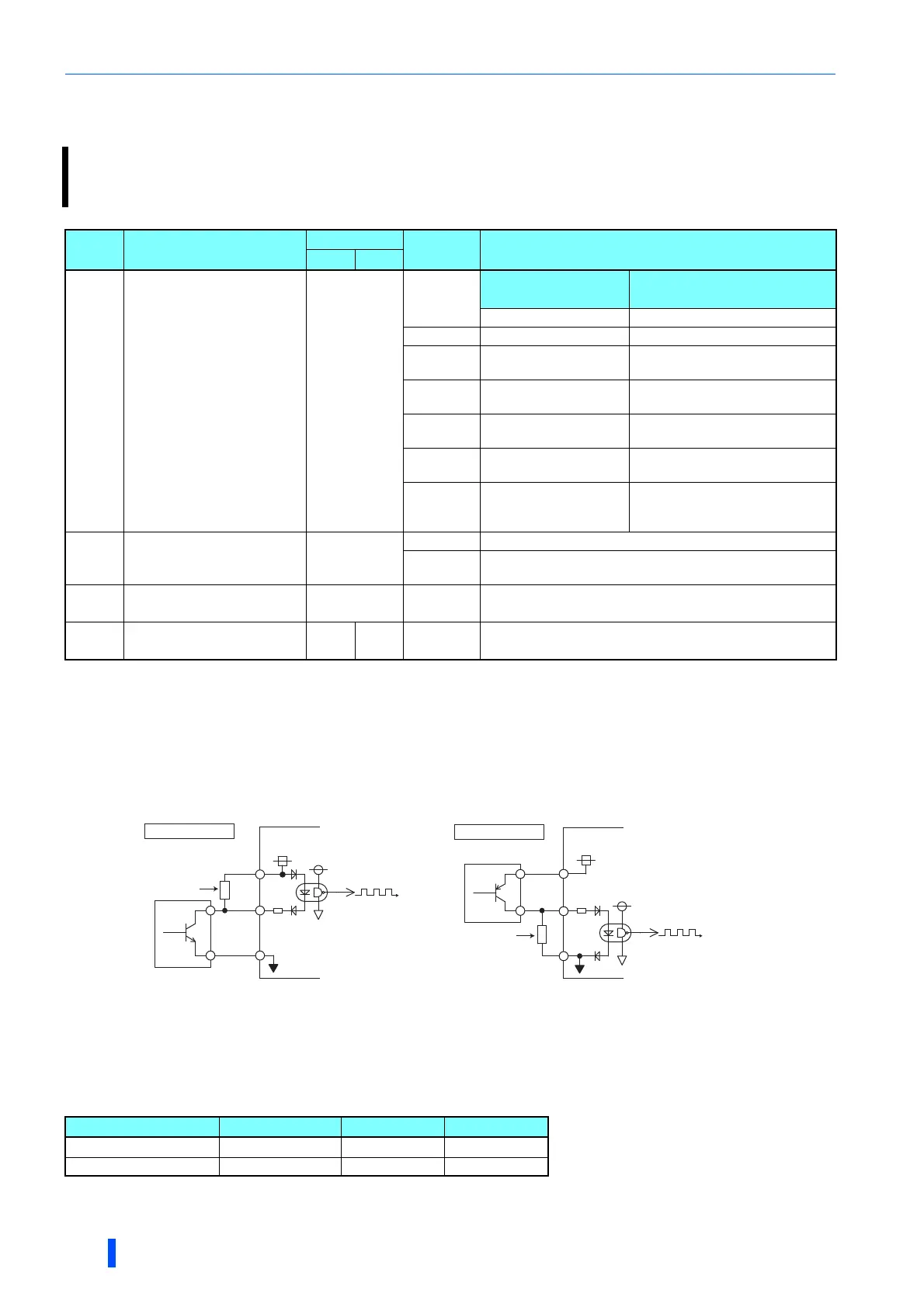
• Connection with an open collector output system pulse generator
When the wiring length is long with open collector outputs, the influence of stray capacitance causes the pulse to flatten out and prevents the
input pulse from being recognized.
When the wiring length is long (10 m or longer of shielded twisted pair cable with a recommended cable gauge of 0.75 mm
2
), connect the open
collector output signal to the power supply by an external pull-up resistance. The table below shows the reference resistance values for wiring
length. The stray capacitance of the wiring changes considerably according to how the cable is laid, thus the above wiring lengths are not
guaranteed values. When using a pull-up/down resistance, check the permissible load of the resistor and the permissible load current of the
output transistor, and use within the permissible range.
A pulse train input to the terminal JOG can be used to set the inverter's speed command.
Moreover, speed synchronized operation of an inverter can be performed by using the pulse train output together with
the terminal JOG.
Pr. Name
Initial value
Setting
range
Description
FM CA
291
D100
Pulse train I/O selection
0
Pulse train input
(terminal JOG)
Pulse train output
(terminal FM)
0 JOG signal FM output
1 Pulse train input FM output
10 JOG signal
High-speed pulse train output (50%
duty)
11
Pulse train input
High-speed pulse train output (50%
duty)
20
JOG signal
High-speed pulse train output (ON
width is fixed)
21
Pulse train input
High-speed pulse train output (ON
width is fixed)
100
Pulse train input
High-speed pulse train output (ON
width is fixed)
Output of pulse train input as is
384
D101
Input pulse division
scaling factor
0
0 Pulse train input disabled
1 to 250
Division ratio on the input pulse. The frequency resolution on
the input pulse changes according to this setting.
385
D110
Frequency for zero input
pulse
0 Hz 0 to 590 Hz Sets the frequency when the input pulse is zero (bias).
386
D101
Frequency for maximum
input pulse
60 Hz 50 Hz 0 to 590 Hz Sets the frequency when the input pulse is maximum (gain).
Wiring length Less than 10 m 10 to 50 m 50 to 100 m
Pull-up/down resistance Not required
1 k
470
Load current (reference) 10 mA 35 mA 65 mA
JOG
PC
SD
Sink logic
Inverter
Pull up resistance ∗1
2kΩ
JOG
PC
SD
Source logic
Inverter
Pull down resistance ∗1
2kΩ

 Loading...


