(G) Control parameters
PARAMETERS
617
5
GROUP
G
Logic reversing of inverter run enable signal (X10 signal, Pr.599)
• Relationship between Pr.599 and the inverter operation enable signal of each option unit
NOTE
• If the X10 signal is unassigned while Pr.30 = "2" (FR-HC2/FR-CV connection) or "10 or 11" (DC feeding mode 1), the MRS
signal can be used as the X10 signal. At this time, logic setting for the signal will follow Pr.17 MRS input selection.
• MRS signal is enabled from any of the communication or external input, but when using the MRS signal as Inverter run
enable signal (X10), it can be used as input from external.
• When FR-HC or MT-HC is connected, set Pr.599 = "0 (initial value)".
• When the terminal assignment is changed with Pr.178 to Pr.189 (input terminal function selection), wiring may be
mistaken due to different terminal name and signal contents, or may affect other functions. Set parameters after confirming
the function of each terminal.
Regenerative brake usage rate alarm output and alarm signal (RBP
signal) (Standard models)
NOTE
• When Pr.30 = "0 (initial value), 10 or 20" for FR-A820-00630(11K) or higher and FR-A840-00310(11K) or higher, the RB
display is disabled.
• When the terminal assignment is changed with Pr.190 to Pr.196 (output terminal function selection), wiring may be
mistaken due to different terminal name and signal contents, or may affect other functions. Set parameters after confirming
the function of each terminal.
Reset when the power is supplied to the main circuit (Pr.30 = "100, 101,
102, 110, 111, 120 or 121")
• While the power is supplied only to the control circuit (R1/L11, S1/L12 input or 24 V external power supply) with Pr.30 =
"100 or higher", the inverter reset is not performed when the power is supplied (R/L1, S/L2, T/L3 input) to the main circuit.
• When a communication option, etc. is used, communication interruption due to the inverter reset can be avoided.
NOTE
• When the power is supplied to the main circuit while the inverter protective function is activated, the inverter reset is
performed even if it the setting is "No reset" at power ON.
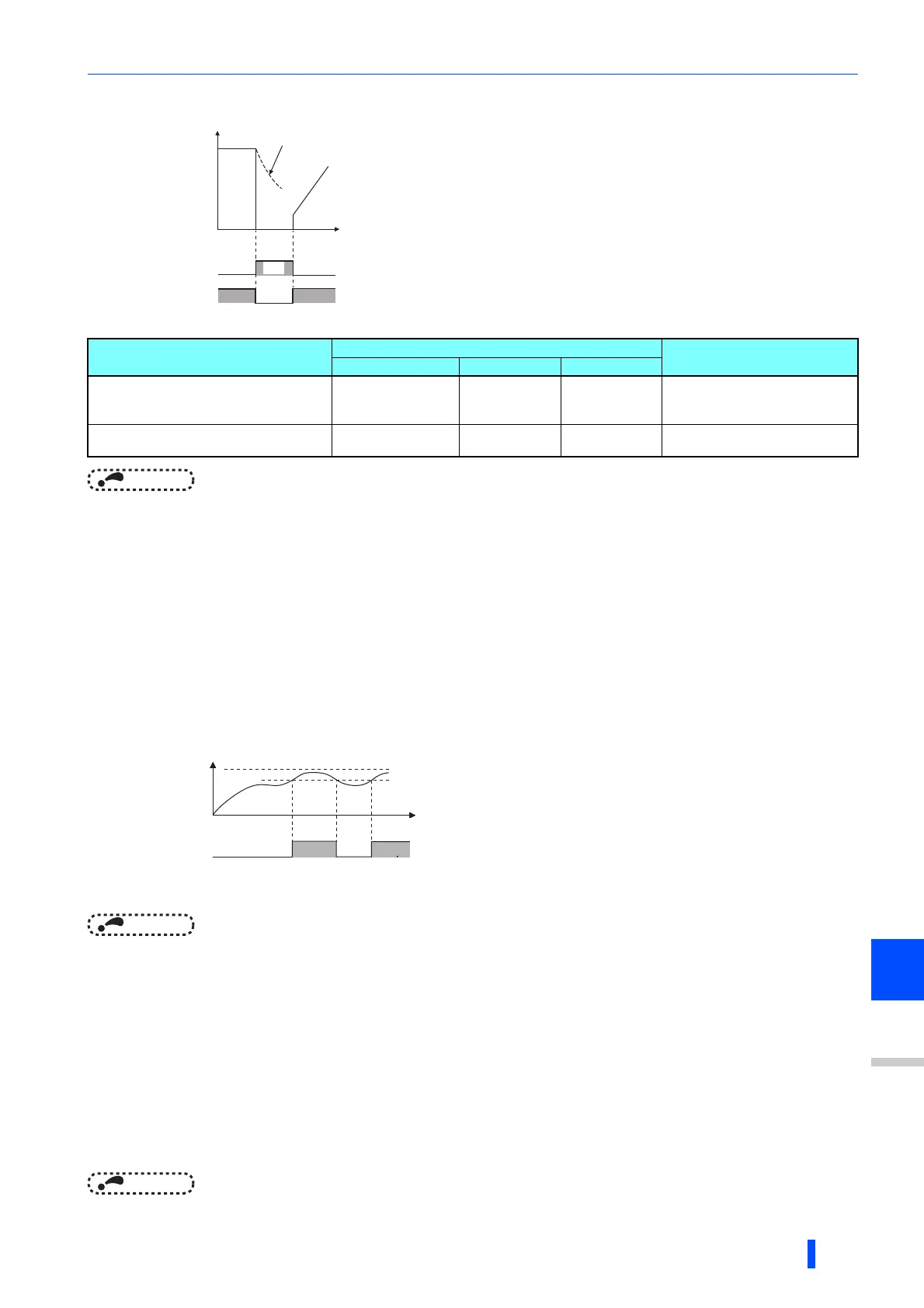
• Use Pr.599 X10 terminal input selection to select the X10 signal input
specification between normally open (NO contact) and normally closed
(NC contact). With the normally closed (NC contact) input specification,
the inverter output is shut off by turning OFF (opening) the X10 signal.
• Changing the inverter logic (NO/NC contact) with the Pr.599 setting is
required according to the logic of the inverter operation enable signal
sent from the option unit.
• The response time of the M10 signal is within 2 ms.
Pr.599 setting
Corresponding signals of the option units Operation according to the
X10 signal status
FR-HC2 FR-CV FR-CC2
0
(Initial value of standard models and IP55
compatible models)
RDY (negative logic)
(initial setting)
RDYB RDB
X10-ON: Inverter output shutoff
(NO contact)
1
(Initial value of separated converter types)
RDY (positive logic) RDYA RDA
X10-OFF: Inverter output shutoff
(NC contact)
100%: Regeneration overvoltage protection operation value
• When the usage rate of regenerative brake reaches 85% of the
Pr.70 setting, [RB] is displayed on the operation panel and
alarm signal (RBP) is output. When it reaches 100% of the
Pr.70 setting, it will become regenerative overvoltage (E.OV[]).
• The inverter will not shutoff output with the alarm signal.
• For the terminal to be used for the RBP signal output, set "7
(positive logic) or 107 (negative logic)" to one of Pr.190 to
Pr.196 (output terminal function selection), and assign the
function.
ON
OFF
X10 signal (Pr.599=0)
Time
Motor coasts to stop
Output frequency
X10 signal (Pr.599=1)
Ratio of brake duty
to the Pr. 70 setting
Regenerative
brake pre-alarm
(RBP)
Time
OFF
ON
100%
85%
ON

 Loading...


