Operation steps
INTRODUCTION
15
1
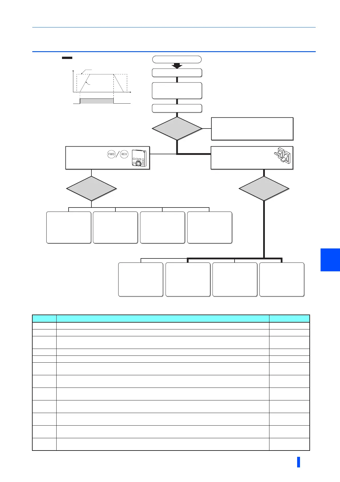
1.3 Operation steps
Symbol Overview Refer to page
(a) Install the inverter. 26
(b) Perform wiring for the power supply and the motor. 38
(c)
Select the control method (V/F control, Advanced magnetic flux vector control, vector control, or PM
sensorless vector control).
164
(d) Input the start command via communication. 555
(e) The PU gives both start and frequency commands. (PU operation mode) 107
(f)
The PU gives a start command, and inputs to terminal RH, RM, and RL give a frequency command.
(External/PU combined operation mode 2)
109
(g)
The PU gives a start command, and voltage input to terminal 2 gives a frequency command.
(External/PU combined operation mode 2)
110
(h)
The PU gives a start command, and current input to terminal 4 gives a frequency command.
(External/PU combined operation mode 2)
111
(i)
Inputs to terminal STF and STR give a start command, and the PU gives a frequency command.
(External/PU combined operation mode 1)
112
(j)
Inputs to terminal STF and STR give a start command, and inputs to terminal RH, RM, and RL give a
frequency command. (External operation mode)
114
(k)
Inputs to terminal STF and STR give a start command, and voltage input to terminal 2 gives a frequency
command. (External operation mode)
115
(l)
Inputs to terminal STF and STR give a start command, and current input to terminal 4 gives a frequency
command. (External operation mode)
117
ON
Frequency
Time
(S)
(Hz)
Start command
Frequency command
Inverter
output
frequency
Step of operation
Installation/mounting
Control mode selection
Wiring of the power
supply and motor
Connect a switch, relay, etc.
to the control circuit
terminal block of the inverter
to give a start command. (External)
Start command using the PU
connector and RS-485 terminal of
the inverter and plug-in option
(Communication)
Set from the
PU (operation panel/
parameter unit).
(PU)
Set from the
PU (operation panel/
parameter unit).
Change of frequency
with ON/OFF switches
connected to terminals
(multi-speed setting)
(External) (External)
(PU) (External) (External) (External)
How
to give a start
command?
How to
give a frequency
command?
(a)
(b)
(c)
(d)
(e) (f) (g) (h)
(i) (j) (k) (l)
Perform frequency
setting by a current
output device
(Connection across
terminals 4 and 5)
Perform frequency
setting by a voltage
output device
(Connection across
terminals 2 and 5)
Perform frequency
setting by a current
output device
(Connection across
terminals 4 and 5)
Perform frequency
setting by a voltage
output device
(Connection across
terminals 2 and 5)
How to
give a frequency
command?
Change frequency
with ON/OFF switches
connected to terminals
(multi-speed setting)
(External)
Start command with
on the operation panel (PU)
: Initial setting

 Loading...


