(M) Monitor display and monitor output signal
PARAMETERS
391
5
GROUP
M
Fault output signals (ALM, ALM2)
NOTE
• For the inverter fault details, refer to page 645.
Input MC shutoff signal (Y91)
• The Fault output 3 (Y91) signal is output when a fault originating in the inverter circuit or a connection fault occurs.
• To use the Y91 signal, set "91 (positive logic) or 191 (negative logic)" in any of Pr.190 to Pr.196 (output terminal
function selection) to assign the function to the output terminal.
• The following table shows the faults that output the Y91 signal. (For the fault details, refer to page 645.)
Pr.13 Starting frequency page 298, page 299
Pr.76 Fault code output selection page 402
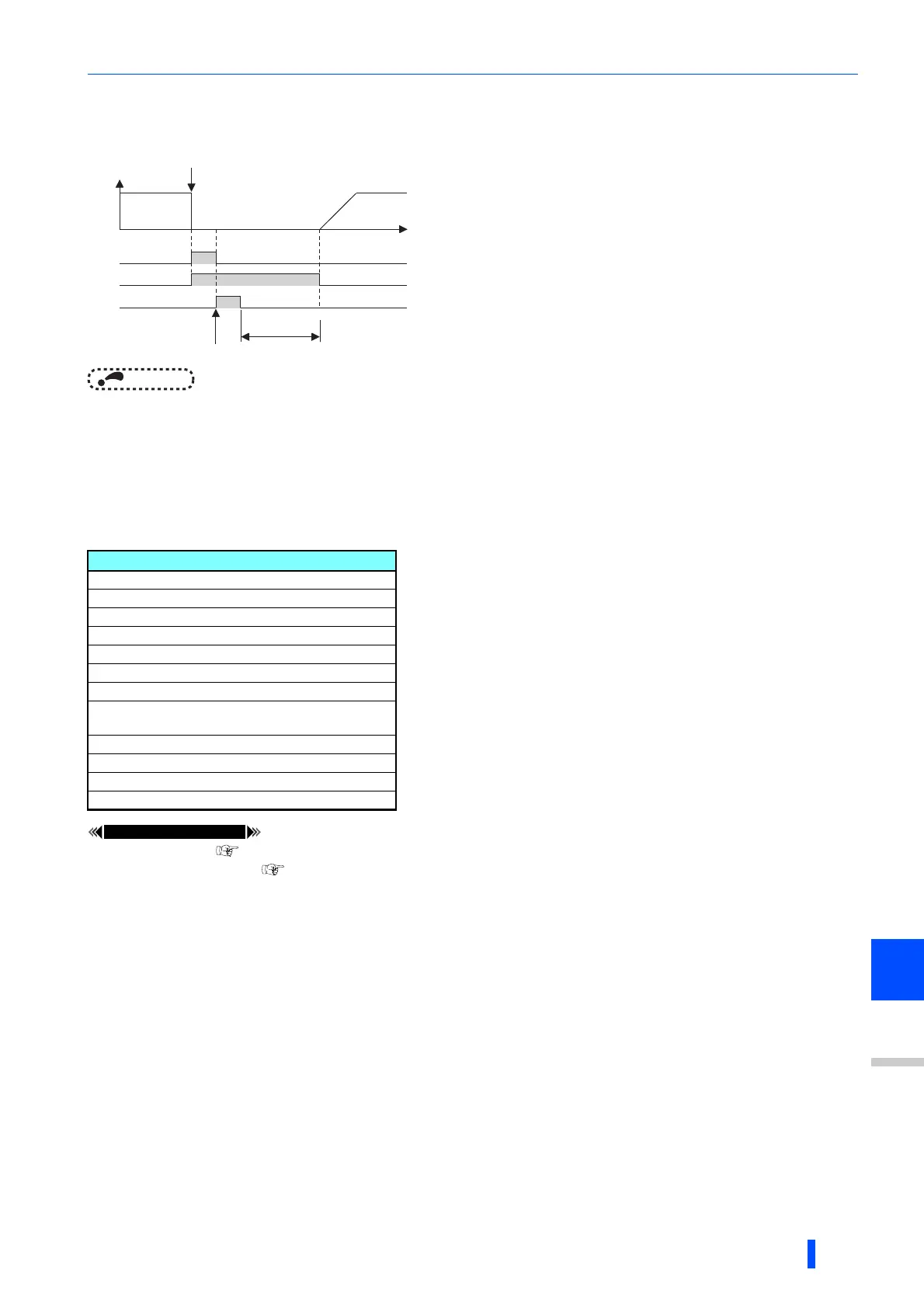
• The Fault (ALM, ALM2) signals are output when the inverter
protective function is activated.
• The ALM2 signal stays ON during the reset period after the fault
occurs.
• To use the ALM2 signal, set "94 (positive logic) or 194 (negative
logic)" in any of Pr.190 to Pr.196 (output terminal function
selection) to assign the function to the output terminal.
• The ALM signal is assigned to the A1B1C1 contacts in the initial
status.
Fault record
Inrush current limit circuit fault (E.IOH)
CPU fault (E.CPU)
CPU fault (E.6)
CPU fault (E.7)
Parameter storage device fault (E.PE)
Parameter storage device fault (E.PE2)
24 VDC power fault (E.P24)
Operation panel power supply short circuit/RS-485
terminals power supply short circuit (E.CTE)
Output side earth (ground) fault overcurrent (E.GF)
Output phase loss (E.LF)
Brake transistor alarm detection (E.BE)
Internal circuit fault (E.13/E.PBT)
ON
OFF
ON
ON
OFF
Reset ON
Output frequency
ALM
LM2
RES
OFF
Inverter fault occurrence
(trip)
Reset processing
(about 1s)
Time

 Loading...


