(M) Monitor display and monitor output signal
PARAMETERS
395
5
GROUP
M
5.11.8 Output current detection function
Output current detection (Y12 signal, Pr.150, Pr.151, Pr.166, Pr.167)
The output current during inverter running can be detected and output to the output terminal.
Pr. Name Initial value Setting range Description
150
M460
Output current detection
level
150% 0 to 220%
Set the output current detection level.
100% is the rated inverter current.
151
M461
Output current detection
signal delay time
0 s 0 to 10 s
Set the output current detection time. Set the time
from when the output current reaches the setting or
higher until the output current detection (Y12) signal
is output.
152
M462
Zero current detection
level
5% 0 to 220%
Set the zero current detection level.
The rated inverter current is regarded as 100%.
153
M463
Zero current detection
time
0.5 s 0 to 10 s
Set the time from when the output current drops to
the Pr.152 setting or lower until the zero current
detection (Y13) signal is output.
166
M433
Output current detection
signal retention time
0.1 s
0 to 10 s Set the retention time when the Y12 signal is ON.
9999
Retain the Y12 signal ON status. The signal is turned
OFF at the next start.
167
M464
Output current detection
operation selection
0 0, 1, 10, 11
Select the operation when Y12 and Y13 signals turn
ON.
• The output current detection function can be used for purposes such
as overtorque detection.
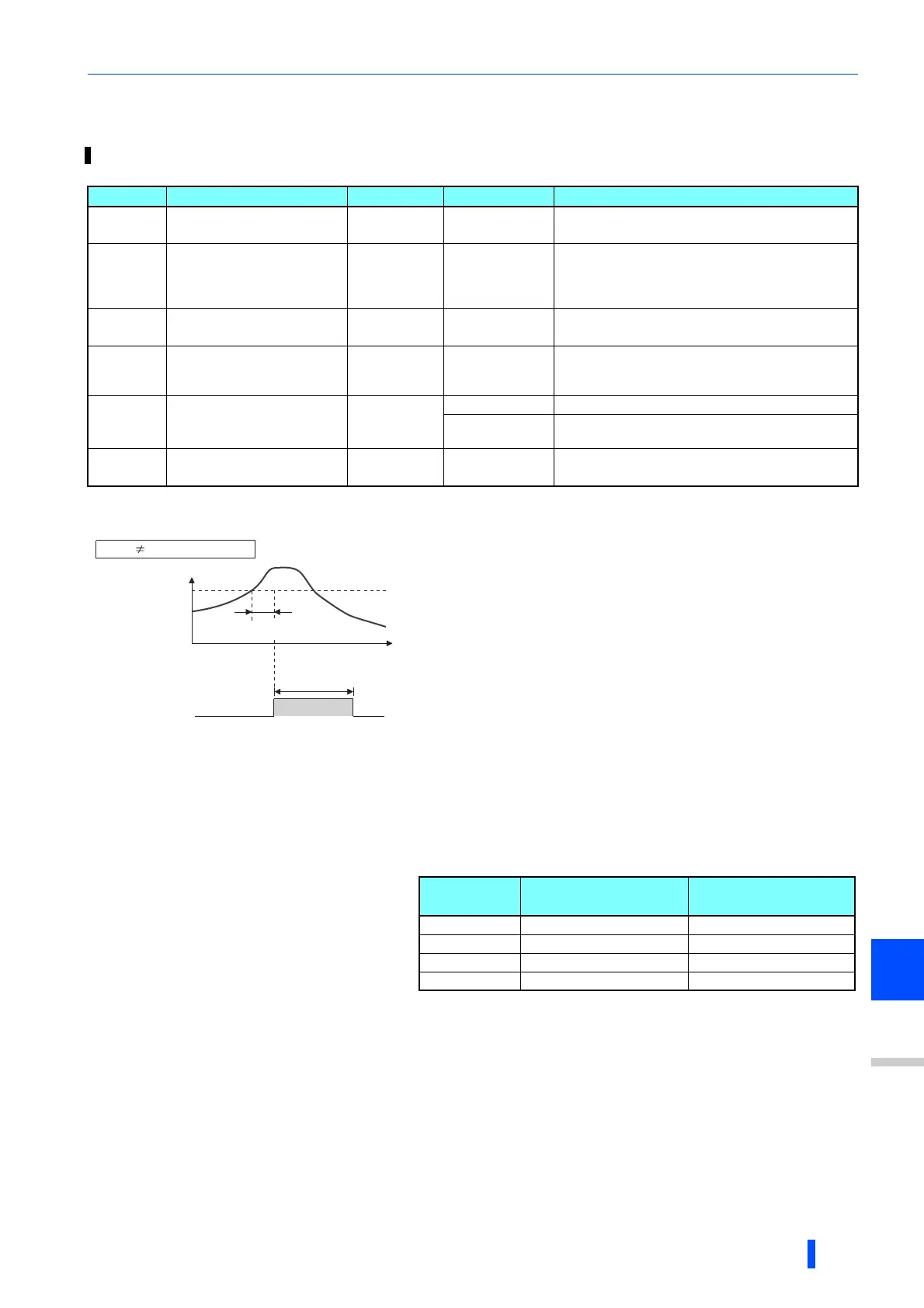
• If the output during inverter running remains higher than the Pr.150
setting for the time set in Pr.151 or longer, the Output current detection
(Y12) signal is output from the inverter's open collector or relay output
terminal.
• When the Y12 signal turns ON, the ON state is retained for the time set
in Pr.166.
• When Pr.166 = "9999", the ON state is retained until the next start.
• Setting Pr.167 = "1" while the Y12 signal is ON does not cause E.CDO.
The Pr.167 setting becomes valid after the Y12 signal is turned OFF.
• For the Y12 signal, set "12 (positive logic) or 112 (negative logic)" in
any of Pr.190 to Pr.196 (output terminal function selection) to
assign the function to the output terminal.
• Select whether the inverter output stops or the inverter operation
continues when Y12 signal turns ON, by setting Pr.167.
Time
Pr.150
OFF
ON
OFF
Output current
detection signal
(Y12)
Pr.166
Minimum 0.1s
(initial value)
Output current
Pr.166 "9999", Pr.167 = "0"
Pr.151
Pr.167
setting
When Y12 signal turns
ON
When Y13 signal truns
ON
0 (Initial value) Continuous operation Continuous operation
1 Inverter trip (E.CDO) Continuous operation
10 Continuous operation Inverter trip (E.CDO)
11 Inverter trip (E.CDO) Inverter trip (E.CDO)

 Loading...


