Connection of stand-alone option units
74
INSTALLATION AND WIRING
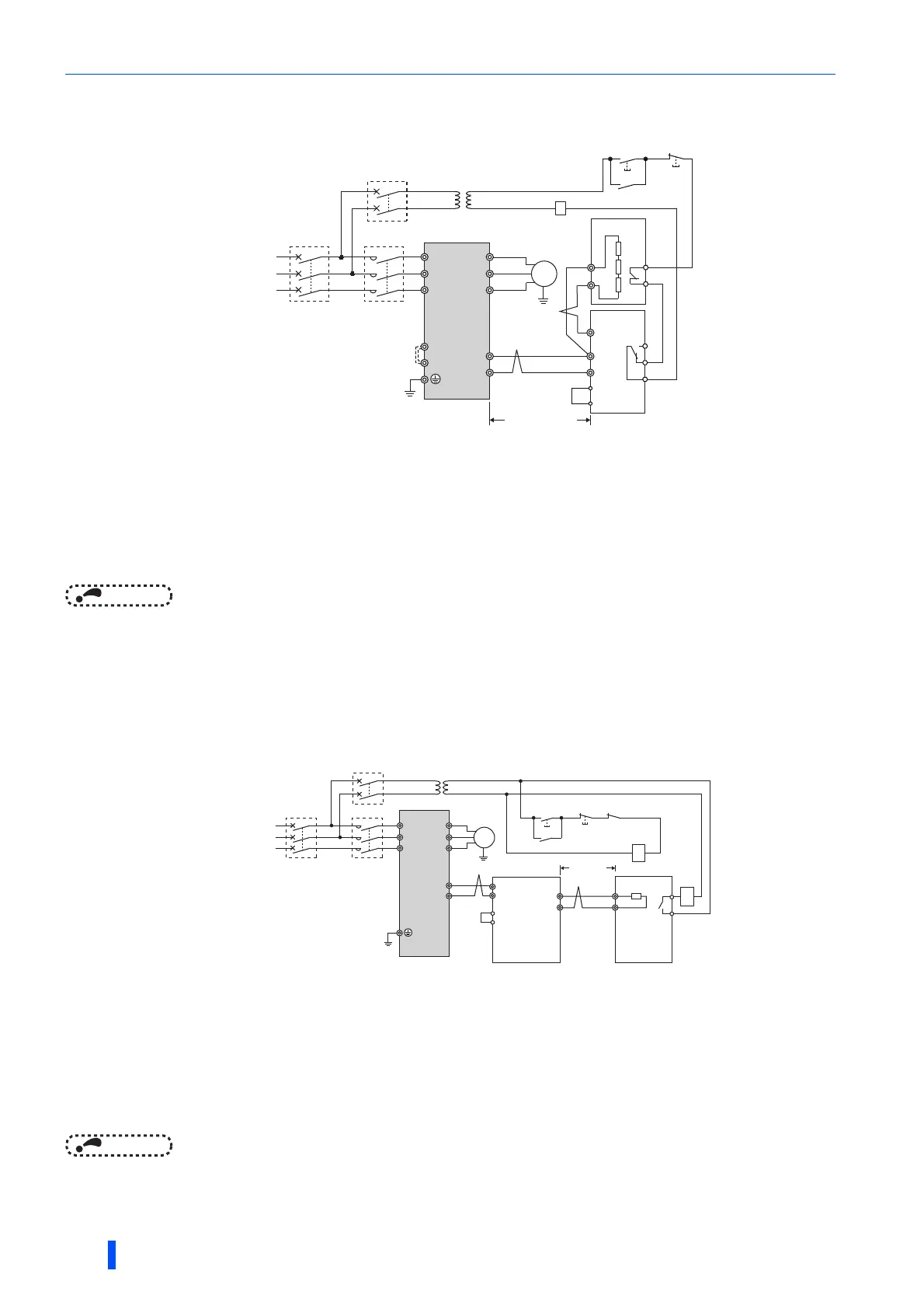
Connection example with the FR-BR-(H) resistor unit
NOTE
• Do not remove the jumper across terminals P/+ and P1 except when connecting a DC reactor (FR-HEL).
Connection example with the MT-BR5 type resistor unit
After wiring securely, set Pr.30 Regenerative function selection = "1" and Pr.70 Special regenerative brake duty = "0
(initial value)".
Set Pr.0 Brake mode selection = "2" in the brake unit FR-BU2.
NOTE
• The stall prevention (overvoltage), oL, does not occur while Pr.30 Regenerative function selection = "1" and Pr.70 Special
regenerative brake duty = "0% (initial value)". (Refer to page 614.)
When wiring, make sure to match the terminal symbol (P/+, N/-) at the inverter side and at the brake unit
(FR-BU2) side. (Incorrect connection will damage the inverter and brake unit.)
When the power supply is 400 V class, install a stepdown transformer.
Be sure to remove the jumper across terminals PR and PX when using the FR-BU2 with the inverter of
FR-A820-00490(7.5K), FR-A840-00250(7.5K) or lower.
The wiring distance between the inverter and brake unit (FR-BU2), and between the brake unit (FR-BU2)
and resistor unit (FR-BR) must be within 5 m. Even when the wire is twisted, the cable length must be
within 10 m.
The contact between TH1 and TH2 is closed in the normal status and is open at a fault.
When wiring, make sure to match the terminal symbol (P/+, N/-) at the inverter side and at the brake unit
(FR-BU2) side. (Incorrect connection will damage the inverter and brake unit.)
When the power supply is 400 V class, install a stepdown transformer.
The wiring distance between the inverter and brake unit (FR-BU2), and between the brake unit (FR-BU2)
and resistor unit (MT-BR5) must be within 5 m. Even when the wire is twisted, the cable length must be
within 10 m.
The contact between TH1 and TH2 is open in the normal status and is closed at a fault.
The CN8 connector used with the MT-BU5 type brake unit is not used.
U
V
W
P/+
N/-
R/L1
S/L2
T/L3
Motor
M
Inverter
PR
N/-
BUE
SD
P/+
P
A
B
C
FR-BU2
FR-BR
TH2
TH1
PR
Three phase AC
power supply
MCCB
MC
OFFON
MC
T ∗2
∗1
10 m or less
MC
PR
PX
∗4
∗4
∗3
∗5
MC
R/L1
Motor
M
Inverter
S/L2
T/L3
U
V
P/+
N/-
P
PR
10m or
less
W
Three phase
C power
supply
MCCB
TH1
TH2
MC
CR1
OFFON
MC
CR1
T
∗2
∗3
∗1
∗3
∗5
∗4
P
N
BUE
SD
P
PR
Brake unit
FR-BU2
Resistor unit
MT-BR5

 Loading...


