Operation panel (FR-DU08)
98
BASIC OPERATION
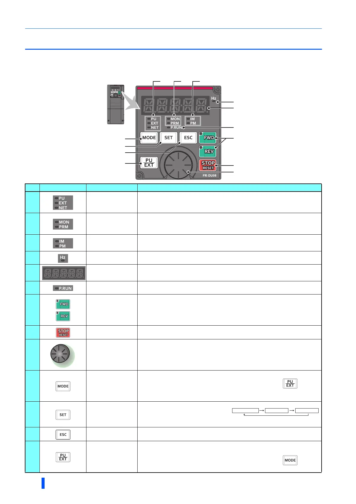
4.1 Operation panel (FR-DU08)
4.1.1 Components of the operation panel (FR-DU08)
To mount the operation panel (FR-DU08) on the enclosure surface, refer to page 59.
No. Component Name Description
(a)
Operation mode
indicator
PU: ON to indicate the PU operation mode.
EXT: ON to indicate the External operation mode. (ON at power-ON in the initial setting.)
NET: ON to indicate the Network operation mode.
PU and EXT: ON to indicate the External/PU combined operation mode 1 or 2.
(b)
Operation panel
status indicator
MON: ON to indicate the monitoring mode. Quickly flickers twice intermittently while
the protective function is activated.
Slowly flickers in the display-off mode.
PRM: ON to indicate the parameter setting mode.
(c)
Control motor
indicator
IM: ON to indicate the induction motor control.
PM: ON to indicate the PM sensorless vector control.
The indicator flickers when test operation is selected.
(d)
Frequency unit
indicator
ON to indicate frequency. (Flickers when the set frequency is displayed in the
monitor.)
(e)
Monitor (5-digit LED)
Shows the frequency, parameter number, etc.
(Using Pr.52, Pr.774 to Pr.776, the monitored item can be changed.)
(f)
PLC function
indicator
ON to indicate that the sequence program can be executed.
(g)
FWD key, REV key
FWD key: Starts forward rotation. The LED is on during forward operation.
REV key: Starts reverse rotation. The LED is on during reverse operation.
The LED flickers under the following conditions.
• When the frequency command is not given even if the forward/reverse command is given.
• When the frequency command is the starting frequency or lower.
• When the MRS signal is being input.
(h)
STOP/RESET key
Stops the operation commands.
Resets the inverter when the protection function is activated.
(i)
Setting dial
The setting dial of the Mitsubishi inverters. The setting dial is used to change the
frequency and parameter settings.
Press the setting dial to perform the following operations:
•
To display a set frequency in the monitoring mode (the setting can be changed using
Pr.992
.)
• To display the present setting during calibration
• To display a fault history number in the faults history mode
(j)
MODE key
Switches to different modes.
Switches to the easy setting mode by pressing simultaneously with .
Holding this key for 2 seconds locks the operation. The key lock is invalid when
Pr.161="0 (initial setting)". (Refer to page 263.)
(k)
SET key
Enters each setting.
If pressed during operation, the monitored
item changes.
(Using Pr.52, Pr.774 to Pr.776, the monitored item can be changed.)
(l)
ESC key
Goes back to the previous display.
Holding this key for a longer time changes the mode back to the monitor mode.
(m)
PU/EXT key
Switches between the PU operation mode, the PUJOG operation mode, and the
External operation mode.
Switches to the easy setting mode by pressing simultaneously with .
Cancels the PU stop also.
(a) (b) (c)
(d)
(e)
(g)
(f)
(h)
(i)
(j)
(k)
(l)
(m)
Output frequency
When the initial setting is set
Output current Output voltage

 Loading...


