Connection of stand-alone option units
78
INSTALLATION AND WIRING
2.9.7 Connection of the power regeneration converter
(MT-RC)
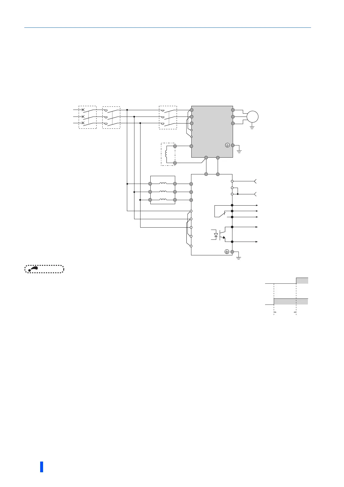
When connecting the power regeneration converter (MT-RC), perform wiring securely as shown below. Incorrect connection
will damage the power regeneration converter and the inverter. The MT-RC is applicable to FR-A840-02160(75K) or higher.
After making sure that the wiring is correct, set "1" in Pr.30 Regenerative function selection and "0" in Pr.70 Special
regenerative brake duty.
NOTE
• When using the inverter with the MT-RC, install a magnetic contactor (MC) at
the input side of the inverter so that power is supplied to the inverter after 1 s or
more has elapsed after powering ON the MT-RC. When power is supplied to
the inverter prior to the MT-RC, the inverter and the MT-RC may be damaged
or the MCCB may trip or be damaged.
• When connecting the power coordination reactor and others, refer to
Instruction Manual of the MT-RC for precautions.
DCL
P1
P1
R/L1
S/L2
T/L3
R1/L11
S1/L21
R
R2
RES
U
V
W
Inverter
MT-RCL
P
P/+ N/-
P
N
RDY
SE
MT-RC
Reset signal
Ready signal
Three-phase
C power
supply
MCCB
MC2
MC1
M
STF
SD
S
T
S2
T2
R2
S2
T2
R
S
T
R1
S1
C
Alarm signal
B
A
MT-RC power
supply (MC1)
Inverter input power
supply (MC2)
ON
ON
1s or more

 Loading...


