Control circuit
INSTALLATION AND WIRING
57
2
Operation while the 24 V external power is supplied
• Faults history and parameters can be read and parameters can be written (when the parameter write from the operation
panel is enabled) using the operation panel keys.
• The safety stop function is invalid during the 24 V external power supply operation.
• During the 24 V external power supply operation, monitored items and signals related to inputs to main circuit power supply,
such as output current, converter output voltage, and IPF signal, are invalid.
• The faults, which have occurred when the main circuit power supply is ON, continue to be output after the power supply is
changed to the 24 V external power supply. Perform the inverter reset or turn OFF then ON the power to reset the faults.
• The retry function is invalid for all faults during the 24 V external power supply.
• If the power supply changes from the main circuit power supply to the 24 V external power supply while measuring the main
circuit capacitor's life, the measurement completes after the power supply changes back to the main circuit power supply
(Pr.259 = "3").
• The output data is retained when "1 or 11" is set in Pr.495 Remote output selection.
NOTE
• Inrush current equal to or higher than the 24 V external power supply specification may flow at power-ON. Confirm that the
power supply and other devices are not affected by the inrush current and the voltage drop caused by it. Depending on the
power supply, the inrush current protection may be activated to disable the power supply. Select the power supply and
capacity carefully.
• When the wiring length between the external power supply and the inverter is long, the voltage often drops. Select the
appropriate wiring size and length to keep the voltage in the rated input voltage range.
• In a serial connection of several inverters, the current increases when it flows through the inverter wiring near the power
supply. The increase of the current causes voltage to drop further. When connecting different inverters to different power
supplies, use the inverters after confirming that the input voltage of each inverter is within the rated input voltage range.
Depending on the power supply, the inrush current protection may be activated to disable the power supply. Select the power
supply and capacity carefully.
• "E.SAF or E.P24" may appear when the start-up time of the 24 V power supply is too long (less than 1.5 V/s) in the 24 V
external power supply operation.
• "E.P24" may appear when the 24 V external power supply input voltage is low. Check the external power supply input.
• Do not touch the control circuit terminal block (circuit board) during the 24 V power supply operation (when conducted).
Otherwise you may get an electric shock or burn.
2.6.7 Safety stop function
Function description
The terminals related to the safety stop function are shown below.
In the initial status, terminals S1 and PC, S2 and PC, and SIC and SD are respectively shorted with shorting wires. To use the safety stop
function, remove all the shortening wires, and then connect to the safety relay module as shown in the following connection diagram.
At an internal safety circuit failure, the operation panel displays one of the faults shown on the next page.
NOTE
• Use the terminal SO to output a fault and to prevent restarting of the inverter. The signal cannot be used as safety stop input
terminal to other devices.
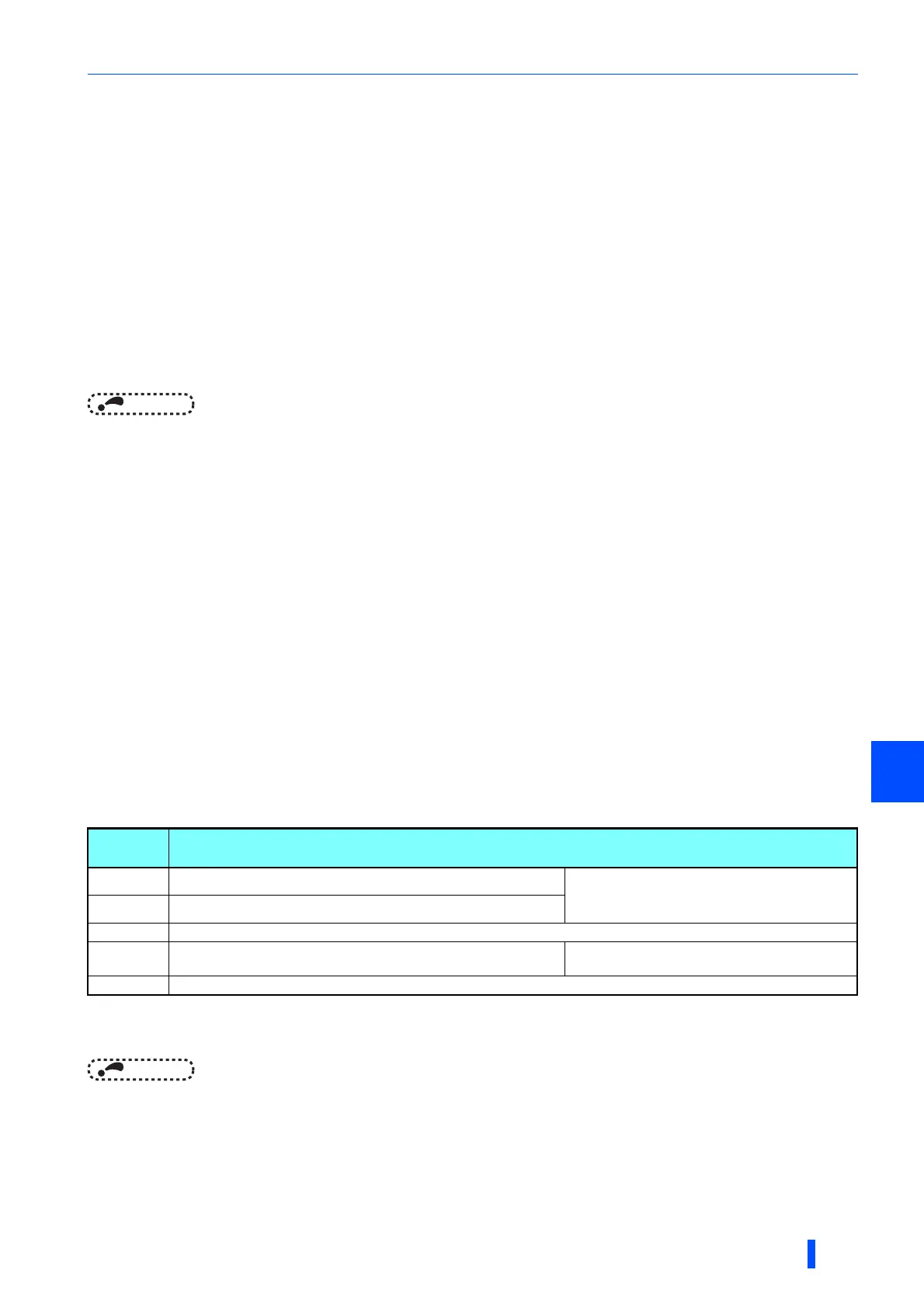
Terminal
symbol
Terminal function description
S1 For input of the safety stop channel 1.
Between S1 and SIC, S2 and SIC
Open: In safety stop mode
Short: Other than the safety stop mode.
S2
For input of the safety stop channel 2.
SIC
Common terminal for S1 and S2.
SO
Outputs when an alarm or failure is detected.
The signal is output when no internal safety circuit failure
exists.
OFF: Internal safety circuit failure
ON: No internal safety circuit failure
SOC Open collector output (terminal SO) common

 Loading...


