(T) Multi-Function Input Terminal Parameters
PARAMETERS
417
5
GROUP
T
Analog input bias/gain calibration (C2 (Pr.902) to C7 (Pr.905), C12
(Pr.917) to C15 (Pr.918))
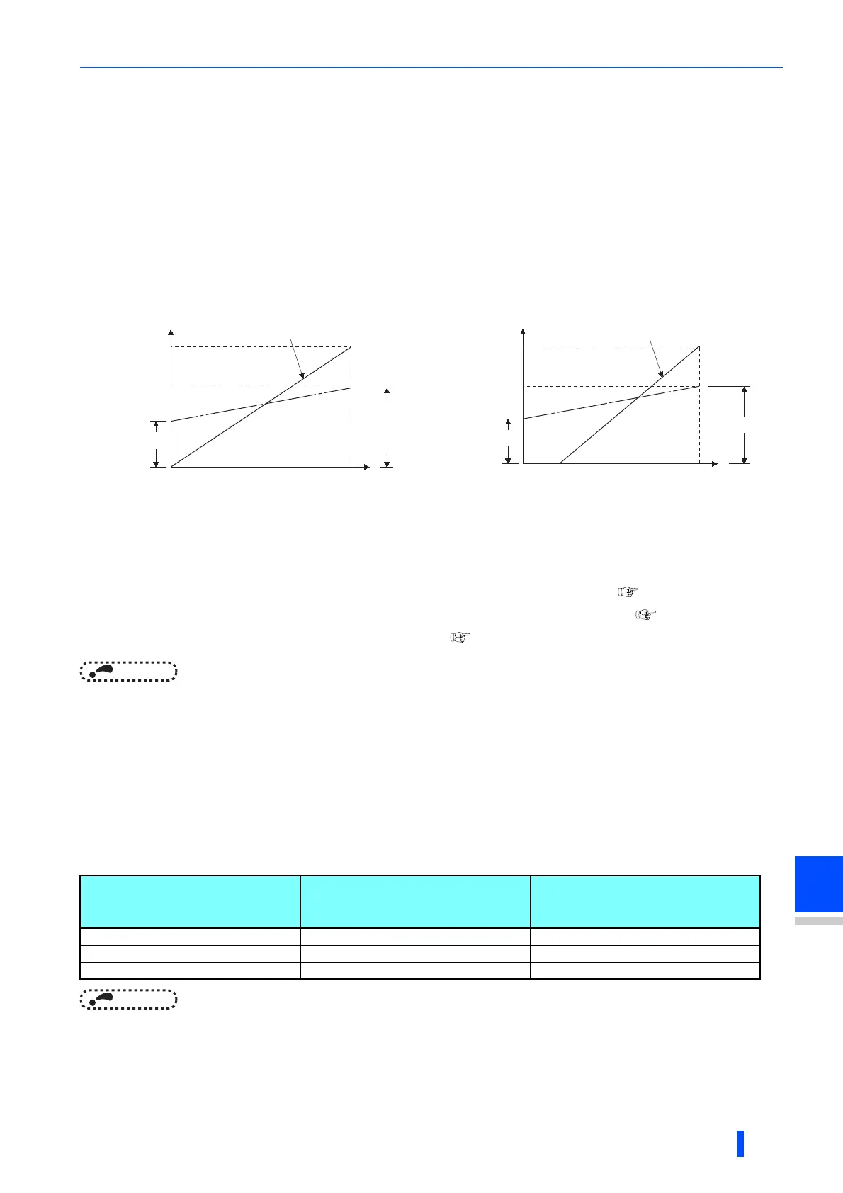
• The "bias" and "gain" functions serve to adjust the relationship between a setting input signal and the output frequency. A
setting input signal is such as 0 to 5 VDC/0 to 10 V or 4 to 20 mADC externally input to set the output frequency.
• Set the terminal 2 input bias frequency by using C2 (Pr.902). (It is initially set to the frequency at 0 V.)
• Set the output frequency to the frequency command voltage (current) set by the Pr.73 Analog input selection by using
Pr.125.
• Set the bias frequency of the terminal 1 input using C12 (Pr.917). (It is initially set to the frequency at 0 V.)
• Set the gain frequency of the terminal 1 input using C14 (Pr.918). (It is initially set to the frequency at 10 V.)
• Set the bias frequency of the terminal 4 input using C5 (Pr.904). (It is initially set to the frequency at 4 mA.)
• Set the output frequency for 20 mA of the frequency command current (4 to 20 mA) by using Pr.126.
• There are three methods to adjust the frequency setting voltage (current) bias/gain.
- Adjust any point with application of a voltage (current) between terminals 2 and 5 (4 and 5). page 418
- Adjust any point without application of a voltage (current) between terminals 2 and 5 (4 and 5). page 419
- Adjust frequency only without adjustment of voltage (current). page 420
NOTE
• Performing terminal 2 calibration that includes a change of the setting frequency incline changes terminal 1 setting.
• Calibration with voltage input to terminal 1 sets (terminal 2 (4) analog value + terminal 1 analog value) as the analog
calibration value.
• Always calibrate the input after changing the voltage/current input signal with Pr.73, Pr.267, and the voltage/current input
selection switch.
Analog input display unit changing (Pr.241)
• The analog input display unit (%/V/mA) for analog input bias and gain calibration can be changed.
• Depending on the terminal input specification set to Pr.73, Pr.267, and voltage/current input switches, the display unit of C3
(Pr.902), C4 (Pr.903), C6 (Pr.904), and C7 (Pr.905) change as described below:
NOTE
• When the terminal 1 input specification (0 to ±5 V, 0 to ±10 V) does not agree with the main speed (terminal 2, terminal 4
input) specification (0 to 5 V, 0 to 10 V, 0 to 20 mA), and if the voltages are applied to terminal 1, the analog input is not
correctly displayed. (For example, in the initial status, when 0 V is applied to terminal 2 and 10 V is applied to terminal 1, and
the analog value is displayed as 5 V (100%).)
Use the inverter with the Pr.241 = "0 (initial value)" setting. (0% display).
Analog command (terminals 2, 4)
(depending on Pr.73, Pr.267, and
voltage/current input switch)
Pr.241 = 0 (initial value) Pr.241 = 1
0 to 5 V input 0 to 5 V 0 to 100% (0.1%) 0 to 100% 0 to 5 V (0.01 V)
0 to 10 V input 0 to 10 V 0 to 100% (0.1%) 0 to 100% 0 to 5 V (0.01 V) display
0 to 20 mA input 0 to 20 mA 0 to 100% (0.1%) 0 to 100% 0 to 20 mA (0.01 mA)
60Hz
(50Hz)
Output frequency
(Hz)
Pr.125
C14(Pr.918)
0
0
0
Frequency setting signal
100%
10V
20mA
Initial value
Bias
Gain
0
5V
C2
C12(Pr.917)
C3(Pr.902)
C13(Pr.917)
C4(Pr.903)
C15(Pr.918)
60Hz
(50Hz)
Pr.126
0
Frequency setting signal
100%
Initial value
Bias
Gain
0
20
4 20mA
Output frequency
(Hz)
C5
(Pr.904)
C6(Pr.904) C7(Pr.905)
01 5V
0 2 10V

 Loading...


