Measurement of main circuit voltages, currents and powers
684
PRECAUTIONS FOR MAINTENANCE AND INSPECTION
Measuring points and instruments
Use an FFT to measure the output voltage accurately. A tester or general measuring instrument cannot measure accurately.
When the carrier frequency exceeds 5 kHz, do not use this instrument since using it may increase eddy current losses produced in metal parts
inside the instrument, leading to burnout. In this case, use an approximate-effective value type.
When the setting of Pr.195 ABC1 terminal function selection is the positive logic
A digital power meter (designed for inverter) can also be used to measure.
Item Measuring point Measuring instrument Remarks (reference measured value)
Power supply voltage
V1
Across R/L1 and S/L2,
S/L2 and T/L3,
T/L3 and R/L1
Moving-iron type AC voltmeter
Commercial power supply
Within permissible AC voltage fluctuation
(Refer to page 690.)
Power supply side
current
I
1
R/L1, S/L2, T/L3 line
current
Moving-iron type AC ammeter
Power supply side
power
P
1
R/L1, S/L2, T/L3 and
Across R/L1 and S/L2,
S/L2 and T/L3,
T/L3 and R/L1
Digital power meter (for inverter) or
electrodynamic type single-phase
wattmeter
P
1 = W11 + W12 + W13 (3-wattmeter method)
Power supply side
power factor
Pf
1
Calculate after measuring power supply voltage, power supply side current and power supply side power.
Output side voltage
V
2
Across U and V, V
and W, and W and U
Rectifier type AC voltage meter
(moving-iron type cannot
measure.)
Difference between the phases is within 1% of the
maximum output voltage.
Output side current
I
2
U, V and W line
currents
Moving-iron type AC ammeter
Difference between the phases is 10% or lower of the
rated inverter current.
Output side power
P
2
U, V, W and
across U and V, V
and W
Digital power meter (for inverter) or
electrodynamic type single-phase
wattmeter
P
2 = W21 + W22
2-wattmeter method (or 3-wattmeter method)
Output side power
factor
Pf
2
Calculate in similar manner to power supply side power factor.
Converter output Across P/+ and N/-
Moving-coil type
(such as tester)
Inverter LED is lit. 1.35 V
1
Frequency setting
signal
Across 2, 4(+) and 5
Moving-coil type
(tester and such may be used.)
(internal resistance 50 k or more)
0 to 10 VDC, 4 to 20 mA
"5" is .
common
Across 1(+) and 5
0 to ±5 VDC and 0 to ±10 VDC
Frequency setting
power supply
Across 10(+) and 5 5.2 VDC
Across 10E(+) and 5 10 VDC
Frequency meter
signal
Across AM(+) and 5
Approximately 10 VDC at maximum
frequency
(without frequency meter)
Across CA(+) and 5
Approximately 20 mADC at maximum
frequency
Across FM(+) and
SD
Approximately 5 VDC at maximum
frequency
(without frequency meter)
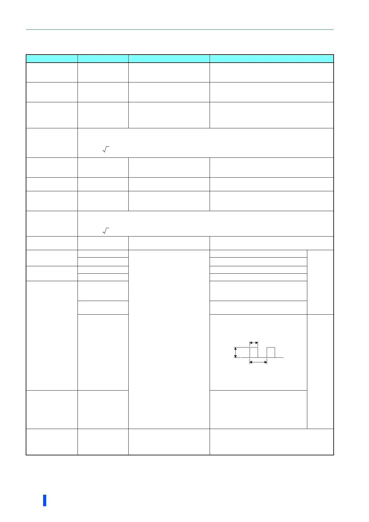
Pulse width T1:
Adjust with
C0 (Pr.900)
.
Pulse cycle T2: Set with Pr.55.
(frequency monitor only)
"SD" is
common
Start signal
Select signal
Reset signal
Output stop signal
Across STF, STR,
RH, RM, RL, JOG,
RT, AU,
STP (STOP)
,
CS, RES, MRS(+)
and SD (for sink
logic)
When open
20 to 30 VDC
ON voltage: 1 V or less
Fault signal
Across A1 and C1
Across B1 and C1
Moving-coil type
(such as tester)
Continuity check
[Normal] [Fault]
Across A1 and C1 Discontinuity Continuity
Across B1 and C1 Continuity Discontinuity
Pf1
P1
3V1 I 1
------------------------
100=
%
Pf2
P2
3V2 I2
------------------------
100=
%
8VDC
T1
T2

 Loading...


