(A) Application parameters
470
PARAMETERS
Pr.11 DC injection brake operation time page 605
Pr.57 Restart coasting time page 528, page 534
Pr.58 Restart cushion time page 528
Pr.79 Operation mode selection page 306
Pr.178 to Pr.189 (input terminal function selection) page 430
Pr.190 to Pr.196 (output terminal function selection) page 384
5.14.2 Self power management
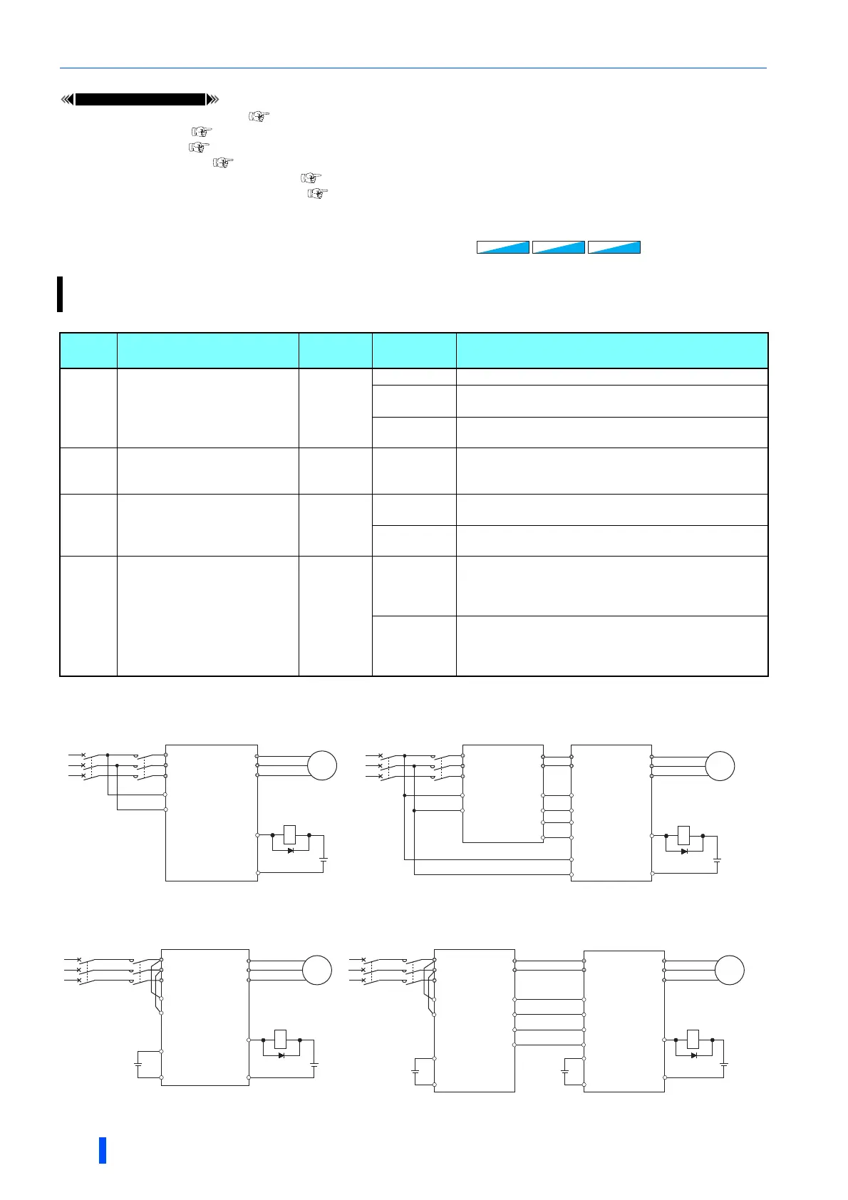
Connection diagram
• Terminal R1, S1 inputs
• 24 V external power supply input
By turning ON the magnetic contactor (MC) on the input side before the motor is started and turning OFF the MC after
the motor is stopped, power is not supplied to the main circuit, reducing the standby power.
Pr. Name
Initial
value
Setting
range
Description
248
A006
Self power management
selection
0
0 Self power management function disabled
1
Self power management function enabled (main circuit OFF
at protective function activation)
2
Self power management function enabled (main circuit OFF
at protective function activation due to a circuit failure)
137
A002
Start waiting time
0.5 s 0 to 100 s
Set a time period that is a little longer than the time period
from the ON signal input to the actual pick-up operation of
MC1 (0.3 to 0.5 s).
254
A007
Main circuit power OFF
waiting time
600 s
0 to 3600 s
Set the waiting time until the main circuit power supply is
turned OFF after the motor is stopped.
9999
The main circuit power supply is turned OFF only when the
protective function selected by Pr.248 is activated.
30
E300
Regenerative function
selection
0
100, 101
Power supply to the inverter: AC (terminals R, S, and T)
When power is supplied only to the control circuit, and then
switched to be supplied to both the control and main
circuits, inverter reset is not performed.
0 to 2, 10, 11,
20, 21, 102,
110, 111, 120,
121
For other settings, refer to page 614.
V/F
V/F
Magnetic flux
Magnetic flux
PM
PM
24VDC
MC1
MC1
R/L1
S/L2
T/L3
R1/L11
S1/L21
U
V
W
M
MC1
SE
MCCB
MC1
Converter unit Inverter
Separated converter type
R/L1
S/L2
T/L3
R1/L11
S1/L21
U
V
W
M
MC1
SE
24VDC
MC1
MCCB
R1/L11
S1/L21
P/+
N/-
P/+
N/-
RDA X10
RSO RES
Y17 X94
SE SD
Standard models
Inverter
MC1
R/L1
S/L2
T/L3
R1/L11
S1/L21
U
V
W
MC1
SE
MCCB
M
24VDC
MC1
+24
SD
24VDC
Converter unit Inverter
MCCB
Separated converter typeStandard models
Inverter
MC1
R/L1
S/L2
T/L3
R1/L11
S1/L21
U
V
W
M
MC1
SE
24VDC
MC1
P/+
N/-
P/+
N/-
RDA X10
RSO RES
+24
SD
+24
SD
24VDC24VDC
Y17 X94
SE SD

 Loading...


