(T) Multi-Function Input Terminal Parameters
412
PARAMETERS
NOTE
• After changing the Pr.73 setting, check the voltage/current input switch setting. Incorrect setting may cause a fault, failure or
malfunction. (For the settings, refer to page 406.)
Override function (Pr.252, Pr.253)
NOTE
• To use terminal 4, the AU signal needs to be turned ON.
• To make compensation input for the multi-speed operation or remote setting, set Pr.28 Multi-speed input compensation
selection = "1" (with compensation) (initial value "0").
• After changing the Pr.73 setting, check the voltage/current input switch setting. Incorrect setting may cause a fault, failure or
malfunction. (For the settings, refer to page 406.)
Pr.28 Multi-speed input compensation selection page 328
Pr.73 Analog input selection page 406
Connection example for the
override function
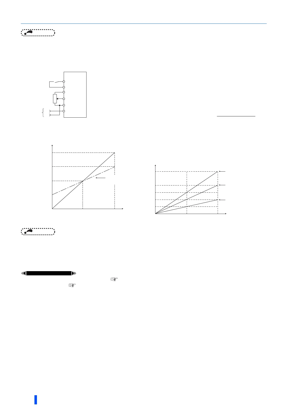
• Use the override function to make the main speed changed at a specified rate.
•Set Pr.73 = "4, 5, 14, or 15" to select the override function.
• When the override function is selected, terminal 1 or 4 is used for the main speed
setting, and terminal 2 is used for the override signal. (if the main speed is not input
to the terminal 1 or 4, the compensation by terminal 2 is disabled.)
• Specify the scope of override by using Pr.252 and Pr.253.
• How to calculate the set frequency for override:
Set frequency (Hz) = main speed setting frequency (Hz)
Main speed setting frequency (Hz): Terminals 1 or 4 input, multi-speed setting
Compensation (%): Terminal 2 input
• Example) When Pr.73 = "5"
By the terminal 1 (main speed) and terminal 2 (auxiliary) input, the
setting frequency is set as shown in the figure below.
10
2
5
Forward
rotation
Main
speed
Inverter
STF
SD
1
(-)
(+)
Override
setting
Pr.252
0V
2.5V
(5V)
5V
(10V)
0
50
100
150
200
Initial value
(50% to 150%)
Voltage across terminals 2 and 5
Pr.253
Override value (%)
0 2.5 5
0
30
15
60
45
90
Terminal 1 input voltage (V)
Terminal 2 5VDC
input(150%)
Terminal 2 2.5VDC
input(100%)
Terminal 2 0V
input(50%)
Set frequency (Hz)

 Loading...


