(G) Control parameters
PARAMETERS
597
5
GROUP
G
5.16.1 Manual torque boost
Initial value for the FR-A820-00077(0.75K) or lower and FR-A840-00038(0.75K) or lower.
Initial values for the FR-A820-00105(1.5K) to FR-A820-00250(3.7K), FR-A840-00052(1.5K) to FR-A840-00126(3.7K).
Initial values for the FR-A820-00340(5.5K), FR-A820-00490(7.5K), FR-A840-00170(5.5K), FR-A840-00250(7.5K).
Initial values for the FR-A820-00630(11K) to FR-A820-03160(55K), FR-A840-00310(11K) to FR-A840-01800(55K).
Initial value for the FR-A820-03800(75K) or higher and FR-A840-02160(75K) or higher.
Starting torque adjustment
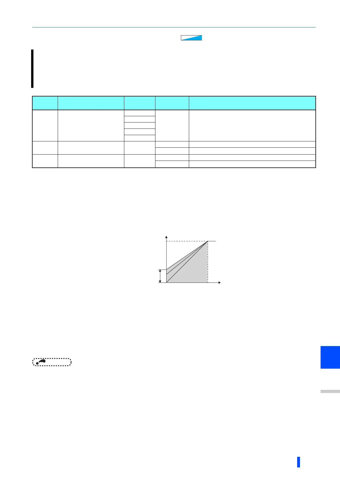
• Assuming Pr.19 Base frequency voltage is 100%, set the output voltage at 0 Hz to Pr.0 (Pr.46, Pr.112) in percentage.
• Perform the adjustment of the parameter little by little (approximately 0.5%), and confirm the status of the motor each time.
The motor may overheat when the value is set too high. Do not use more than 10% as a guideline.
Setting multiple torque boosts (RT signal, X9 signal, Pr.46, Pr.112)
• When changing the torque boost depending on the usage or when using single inverter switching between multiple motors,
use the second (third) torque boost.
• Pr.46 Second torque boost will become enabled when the RT signal turns ON.
• Pr.112 Third torque boost will become enabled when X9 signal turns ON. Set "9" in Pr.178 to Pr.189 (input terminal
function selection) to assign X9 signal function to a terminal.
NOTE
• The RT (X9) signal acts as the second (third) function selection signal and makes the other second (third) functions valid.
(Refer to page 434.)
• The RT signal is assigned to the terminal RT in the initial status. Set "3" in any of Pr.178 to Pr.189 (input terminal function
selection) to assign the RT signal to another terminal.
• Set a larger value when the distance between the inverter and the motor is long or when there is not enough motor torque in
the low-speed range. It may cause overcurrent trip when it is set too large.
• Setting for Pr.0, Pr.46, and Pr.112 becomes enabled only when the V/F control is selected.
• When the initial value is set in Pr.0, the Pr.0 setting is automatically changed by changing the Pr.71 Applied motor setting.
(Refer to page 438)
• Changing the terminal assignment using Pr.178 to Pr.189 (input terminal function selection) may affect the other
functions. Set parameters after confirming the function of each terminal.
Voltage drop in the low-frequency range can be compensated, improving reduction of the motor torque in the low-speed
range.
• Motor torque in the low-frequency range can be adjusted according to the load, increasing the motor torque at the
start up.
• By using the RT signal or X9 signal, it is possible to switch between 3 types of torque boost.
Pr. Name
Initial
value
Setting
range
Description
0
G000
Torque boost
6%
0 to 30% Set the output voltage at 0 Hz in %.
4%
3%
2%
1%
46
G010
Second torque boost
9999
0 to 30% Set the torque boost value at when RT signal is ON.
9999 Without second torque boost
112
G020
Third torque boost
9999
0 to 30% Set the torque boost value at when X9 signal is ON.
9999 Without third torque boost
Output
voltage
Pr.0
Pr.46
Setting
range
Base
frequency
0
100%
Output
frequency
(Hz)
Pr.112

 Loading...


