Speed control under Real sensorless vector control, vector control, PM sensorless vector
control
208
PARAMETERS
5.3.10 Notch filter
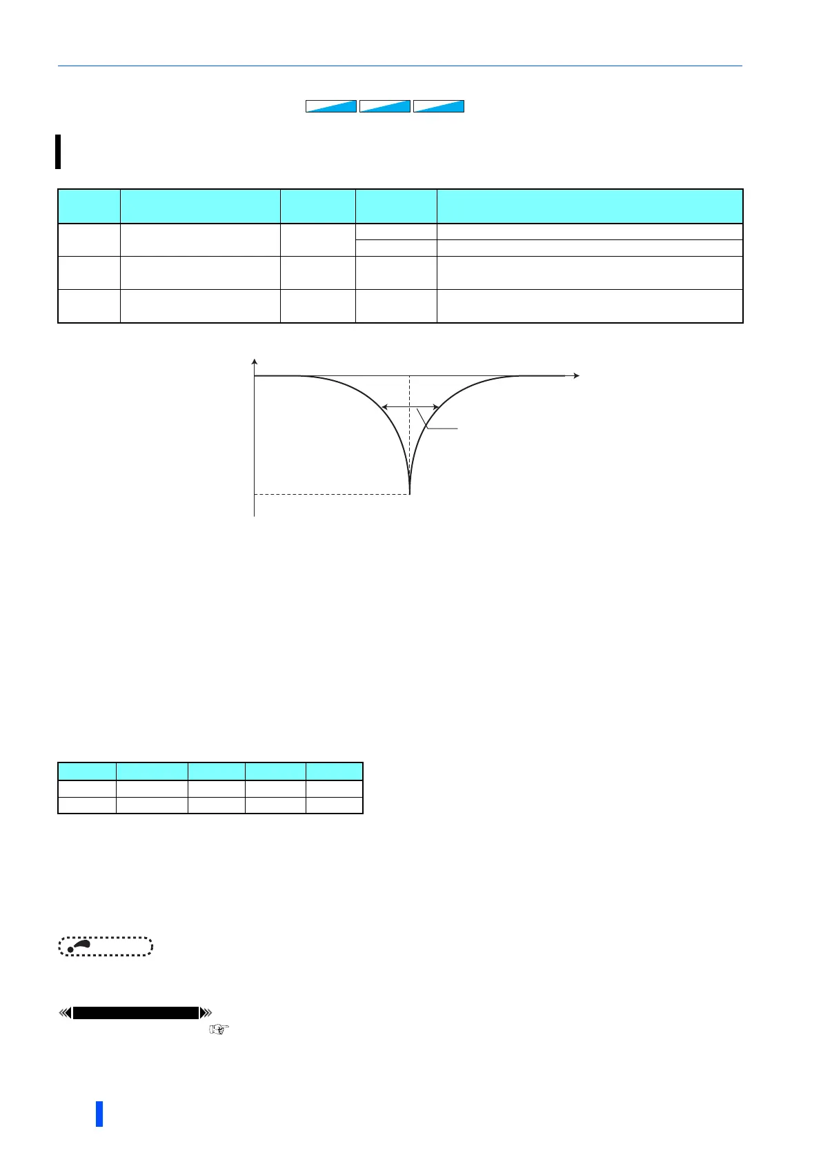
Pr.1003 Notch filter frequency
• This sets the frequency for the center when attenuating the gain. If the mechanical resonance frequency is unknown, lower
the notch frequency in order from the highest. The point where the resonance is smallest is the optimum setting for the
notch frequency.
• The mechanical characteristics can be assessed in advance with a machine analyzer that uses FR Configurator2. This
enables the required notch frequency to be determined.
Pr.1004 Notch filter depth
• A deeper notch depth has a greater effect in reducing mechanical resonance, but because the phase delay is larger,
vibration may increase. Adjust by starting from the shallowest value.
Pr.1005 Notch filter width
• This sets the width of the frequency to which to apply the notch filter. The setting can be adjusted according to the width of
the frequency range to be excluded.
• If the width is too wide, the response level of speed control will drop, and the system may become unstable.
NOTE
• If a value higher than 500 Hz is set in Pr.1003 while the response speed is normal (Pr.800 = any of "0 to 5 and 9 to 14"), the
inverter operates at 500 Hz.
Pr.800 Control method selection page 164
The response level of speed control in the resonance frequency band of mechanical systems can be lowered to avoid
mechanical resonance.
Pr. Name
Initial
value
Setting
range
Description
1003
G601
Notch filter frequency
0
0 No notch filter
8 to 1250 Hz Set the frequency for the center of gain attenuation.
1004
G602
Notch filter depth
0 0 to 3 0 (Deep) 3 (Shallow)
1005
G603
Notch filter width
0 0 to 3 0 (Narrow) 3 (Wide)
Setting 3 2 1 0
Depth Shallow Deep
Gain -4dB -8dB -14dB -40dB
Sensorless
SensorlessSensorless
SensorlessSensorless
Sensorless
Vector
Vector
PM
PM
Gain
Frequency0dB
Pr.1003
Notch filter frequency
Pr.1005
Notch filter width
Pr.1004
Notch filter depth

 Loading...


