(T) Multi-Function Input Terminal Parameters
PARAMETERS
433
5
GROUP
T
5.12.9 Inverter output shutoff signal
Assigning a different action for each MRS signal input via
communication and external terminal (Pr.17 = "4")
• When Pr.17 = "4", the MRS signal from an external terminal can be set as the normally closed (NC contact) input, and the
MRS signal from communication as the normally open (NO contact) input. This function is useful to perform operation by
communication with MRS signal from external terminal remained ON.
NOTE
• The MRS signal is assigned to the terminal MRS in the initial status. By setting "24" in either Pr.178 to Pr.189 (input terminal
function selection), the RT signal can be assigned to the other terminal.
• When using an external terminal to input the MRS signal, the MRS signal shuts off the output in any of the operation modes.
• MRS signal is valid from either of communication or external, but when the MRS signals is to be used as Inverter run enable
signal (X10), it is required to input from external.
• When the terminal assignment is changed using Pr.178 to Pr.189 (input terminal function selection), the terminal name
will be different, which may result in an error of wiring, or affect other functions. Set parameters after confirming the function
of each terminal.
Pr.178 to Pr.189 (input terminal function selection) page 430
The inverter output can be shut off with the MRS signal. The logic of the MRS signal can also be selected.
Pr. Name Initial value Setting range Description
17
T720
MRS input selection
0
0 Normally open input
2
Normally closed input
(NC contact input specification)
4
External terminal: Normally closed
input (NC contact input specification)
Communication: Normally open input
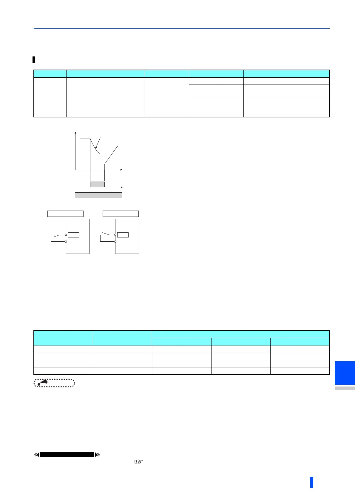
About output shutoff signal (MRS signal)
• When the Output stop (MRS) signal is turned ON while operating the
inverter, the inverter output is instantaneously shut off.
• The response time of the MRS signal is within 2 ms.
• Terminal MRS may be used as described below.
(a) To use a mechanical brake (e.g. electromagnetic brake) to stop the
motor
The inverter output is shut off when the mechanical brake operates.
(b) To provide interlock to disable operation by the inverter
With the MRS signal ON, the inverter cannot be operated even if the
start signal is entered into the inverter.
(c) To coast the motor to a stop
When the start signal is turned OFF, the inverter decelerates the
motor to a stop in the preset deceleration time, but when the MRS
signal is turned ON, the motor coasts to a stop.
MRS signal logic inversion (Pr.17 = "2")
• When Pr.17 = "2", the MRS signal can be changed to normally closed
(NC contact) specification. The inverter will shut off the output with MRS
signal turned ON (opened).
External MRS Communication MRS
Pr.17 setting
0 2 4
OFF OFF Operation enabled Output shutoff Output shutoff
OFF ON Output shutoff Output shutoff Output shutoff
ON OFF Output shutoff Output shutoff Operation enabled
ON ON Output shutoff Operation enabled Output shutoff
ON
ON
MRS signal
STF (STR)
signal
Motor coasts
to stop
Time
(Initial
value)
Output
stop
Output
stop
MRS
SD (PC)
Inverter
MRS
SD (PC)
Inverter
Setting value "0"
Setting value "2"

 Loading...


