(A) Application parameters
PARAMETERS
523
5
GROUP
A
NOTE
• Normally, set Pr.7 Acceleration time and Pr.8 Deceleration time to "0 s". When the Pr.7 and Pr.8 settings are large, dancer
control response becomes slow during acceleration/deceleration.
• The Pr.127 PID control automatic switchover frequency setting is enabled. The larger setting value between Pr.7 and
Pr.44 is used as the acceleration time during normal operation. For the deceleration time, the larger setting value between
Pr.8 and Pr.45 is used. (For the details of Pr.127, refer to page 501.)
• If an automatic restart after instantaneous power failure is activated during dancer control, E.OC[] or E.OV[] is likely to occur.
In such case, disable the automatic restart after instantaneous power failure function (Pr.57 = "9999").
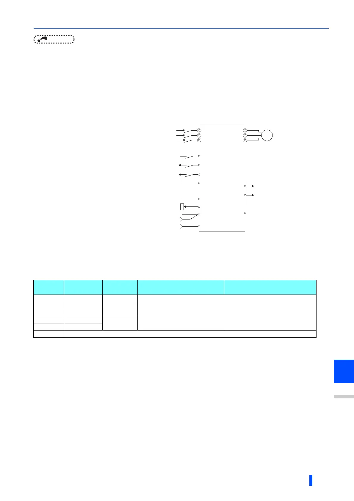
Connection diagram
Dancer control operation selection (Pr.128)
When Pr.133 "9999", the Pr.133 setting is valid.
• To enable dancer control, set "40 to 43" in Pr.128 PID action selection.
• Dancer control is enabled only when the PID control valid terminal (X14) signal turns ON when "14" is set in one of Pr.178
to Pr.182 (Input terminal function selection) and X14 signal is assigned.
When the X14 signal is not assigned, dancer control is enabled only by the Pr.128 setting.
• Input the main speed command (External, PU, Communication). Dancer control is also supported by the main speed
command in all operation modes.
• Input the set point between the terminals 2 and 5 (the setting can be selected using Pr.133 or Pr.609) and input the
measured value signal (dancer roll position detection signal) between the inverter terminals 4 and 5 (the setting can be
selected using Pr.610).
• The action of Pr.129 PID action selection, Pr.130 PID integral time, Pr.131 PID upper limit, Pr.132 PID lower limit and
Pr.134 PID differential time is the same as PID control action. In the relationship between the control amount (%) and
frequency in PID control, 0% and 100% are equivalent to the frequencies set to Pr.902 and Pr.903, respectively.
• Sink logic
• Pr.128 =41
• Pr.182 =14
• Pr.193 =14
• Pr.194 =15
• Pr.133 =set point
The main speed command differs according to each operation mode (External, PU, communication).
The output signal terminal to be used differs according to the Pr.190 to Pr.196 (Output terminal function selection) setting.
The input signal terminal to be used differs according to the Pr.178 to Pr.189 (Input terminal function selection) setting.
The AU signal need not be input.
Pr.128
setting
PID action
Additive
method
Set point input Measured value input
0PID invalid- - -
40 Reverse action
Fixed
Set by Pr.133 or Input by terminal
selected by Pr.609
Input by terminal selected by Pr.610
41 Forward action
42 Reverse action
Ratio
43 Forward action
Others Refer to page 501.
Power supply
MCCB
Inverter
Forward rotation
Reverse rotation
PID control selection
Main speed command
setting potentiometer
∗1
R/L1
S/L2
T/L3
STF
STR
RH(X14)
∗3
SD
10
2
5
4
∗4
U
V
W
∗2 (FUP)FU
SE
Motor
IM
Upper limit
∗2 (FDN)OL Lower limit
Output signal common
Feedback value of
dancer roll position

 Loading...


