Connection of motor with encoder (vector control)
INSTALLATION AND WIRING
63
2
Switches of the FR-A8AP
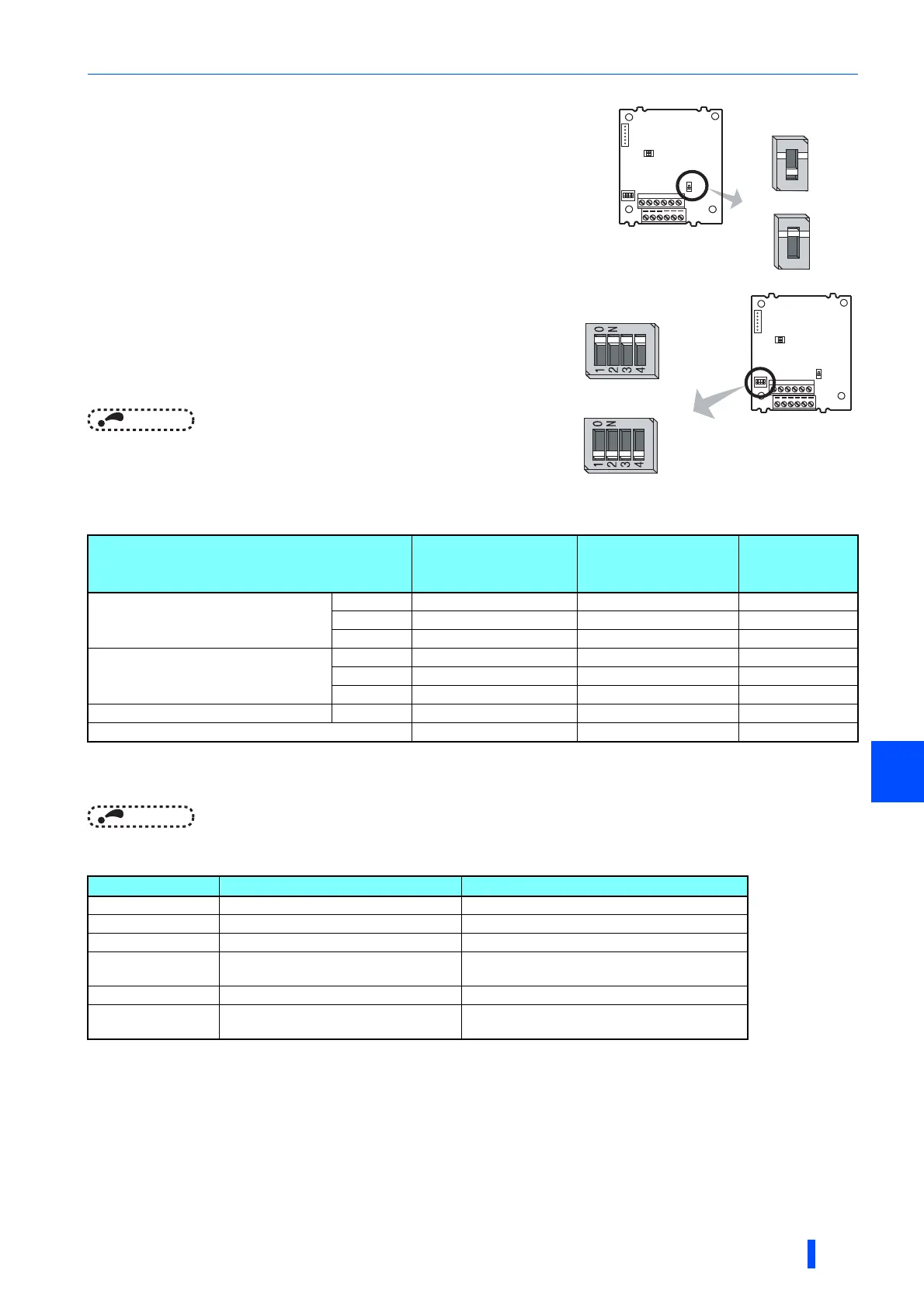
• Encoder type selection switch (SW3)
Selects either the differential line driver or complementary setting.
It is initially set to the differential line driver. Switch its position according to the
output circuit.
• Terminating resistor selection switch (SW1)
Selects ON/OFF of the internal terminating resistor.
Set the switch to ON (initial status) when an encoder output type is differential
line driver, and set to OFF when complementary.
ON: with internal terminating resistor (initial status)
OFF:
without internal terminating resistor
NOTE
• Set all switches to the same setting (ON/OFF).
• Set the switch "OFF" when sharing an encoder with another unit (NC
(computerized numerical controller), etc.) having a terminating resistor
under the differential line driver setting.
• Motor and switch setting
Set according to the motor (encoder).
Prepare an encoder's power supply (5 V/12 V/15 V/24 V) according to the encoder's output voltage.
When the encoder output is the differential line driver type, only 5 V can be input.
NOTE
• The SW2 switch is for manufacturer setting. Do not change the setting.
• Encoder specification
Motor
Encoder type selection
switch (SW3)
Terminating resistor
selection switch
(SW1)
Power supply
specification
Mitsubishi standard motor with encoder
Mitsubishi high-efficiency motor with
encoder
SF-JR Differential ON 5 V
SF-HR Differential ON 5 V
Other
Mitsubishi constant-torque motor with
encoder
SF-JRCA Differential ON 5 V
SF-HRCA Differential ON 5 V
Other
Vector control dedicated motor SF-V5RU Complementary OFF 12 V
Other manufacturer's motor with encoder
Item Encoder for SF-JR Encoder for SF-V5RU
Resolution 1024 pulses/rev 2048 pulses/rev
Power supply voltage 5 VDC ±10% 12 VDC ±10%
Current consumption 150 mA 150 mA
Output signal form
A, B phases (90° phase shift)
Z phase: 1 pulse/rev
A, B phases (90° phase shift)
Z phase: 1 pulse/rev
Output circuit Differential line driver 74LS113 equivalent Complementary
Output voltage
H level: 2.4 V or more
L level: 0.5 V or less
H level: (Power supply for encoder-3 V) or more
L level: 3 V or less
Complementary
Differential line
driver (initial status)
1
2
3
4
O
N
1
2
O
N
SW2
SW3
SW1
Internal terminating
resistor-ON
(initial status)
Internal terminating
resistor-OFF
1
2
3
4
O
N
1
2
O
N
SW2
SW3
SW1

 Loading...


