(A) Application parameters
490
PARAMETERS
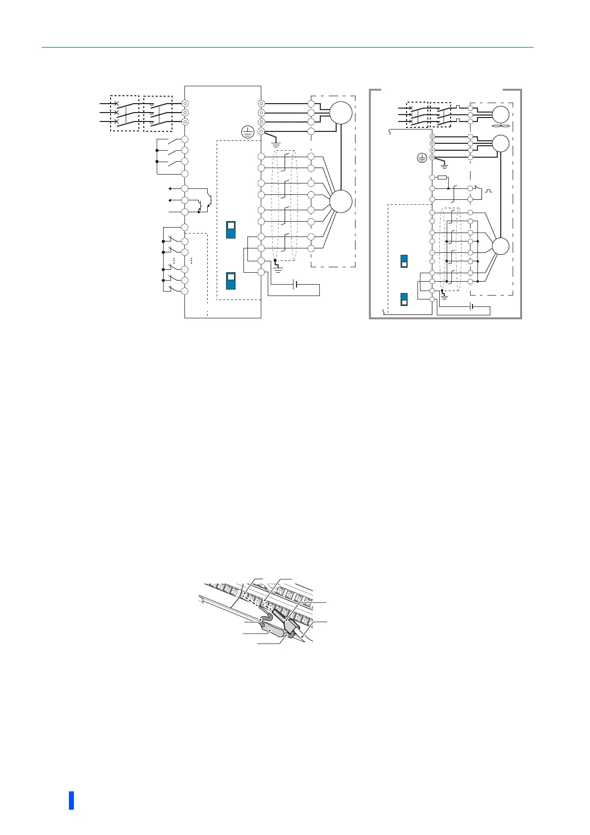
Connection example
The power supply of the fan for a 7.5 kW or lower dedicated motor is single phase. (200 V/50 Hz, 200 to 230 V/60 Hz)
The pin number differs according to the encoder used.
Use Pr.178 to Pr.189 (input terminal function selection) to assign the function to a terminal. (Refer to page 430.)
Use Pr.190 to Pr.196 (output terminal function selection) to assign the function to a terminal. (Refer to page 384.)
Connect the encoder so that there is no looseness between the motor and motor shaft. Speed ratio must be 1:1.
Connect the shield of the encoder cable to the enclosure using a tool such as a P-clip. (Refer to page 67.)
For the differential line driver, set the terminating resistor selection switch to the ON position (initial status) to use. (Refer to page 63.)
Note that the terminating resistor switch should be set to the OFF position when sharing the same encoder with another unit (NC, etc.) or when
the terminating resistor is connected to another unit. For the complementary, set the switch to the OFF position.
For terminal compatibility of FR-JCBL, FR-V5CBL and FR-A8AP, refer to page 65.
A separate power supply of 5 V/12 V/15 V/24 V is necessary according to the encoder power specification. Make the voltage of the external
power supply same as the encoder output voltage, and connect the external power supply between PG and SD. When performing encoder
feedback control and vector control together, an encoder and power supply can be shared.
When a stop position command is input from outside, a plug-in option FR-A8AX is required. Refer to page 491 for the external stop position
command.
Connect the recommended 2W1k resistor between the terminal PC and OH. (Recommended product: MOS2C102J 2W1k by KOA
Corporation)
Insert the input line and the resistor to a 2-wire blade terminal, and connect the blade terminal to the terminal OH. (For the recommended 2-wire
blade terminals, refer to page 51.)
Insulate the lead wire of the resistor, for example by applying a contraction tube, and shape the wires so that the resistor and its lead wire will not
touch other cables. Caulk the lead wire securely together with the thermal protector input line using a 2-wire blade terminal. (Do not subject the
lead wire's bottom area to an excessive pressure.)
To use a terminal as the terminal OH, assign the OH (external thermal O/L relay input) signal to an input terminal. (Set "7" in any of Pr.178 to
Pr.189. For details, refer to the Instruction Manual (Detailed) of the inverter.)
Setting
• If the orientation command signal (X22) is turned ON during operation after the various parameters have been set, the
speed will decelerate to the "orientation switchover speed". After the "orientation stop distance" is calculated, the speed will
further decelerate, and the "orientation state" (servo lock) will be entered. The "orientation complete signal" (ORA) will be
output when the "orientation complete width" is entered.
Three-phase
AC power
supply
MCCB
R/L1
S/L2
T/L3
DY
SF-JR motor with encoder
U
V
W
U
V
W
E
C
∗6
∗2
∗5
∗10
∗7
∗8
∗2
∗5
∗7
∗8
X0
X1
X14
X15
R
PA1
FR-A8AP
PA2
PB1
PB2
PZ1
PZ2
PG
PG
SD
SD
Differential
Terminating
resistor ON
OFF
Complementary
A
N
B
P
H
K
IM
Differential
Terminating
resistor ON
OFF
Complementary
Forward rotation start
Reverse rotation start
Orientation command
Contact input common
STF
STR
SD
SD
X22
∗3
Encoder
Inverter
ORM
ORA
∗4
SE
∗4
FR-A8AX
SF-V5RU
U
V
W
U
A
B
C
V
W
E
G1
G2
A
2W1kΩ
∗6
Three-phase
AC power
supply
MCCB
B
PA1
FR-A8AP
PA2
PB1
PB2
PZ1
PZ2
PG
PG
SD
SD
C
D
F
G
S
R
IM
FAN
Encoder
External
thermal relay
input
∗11
Thermal
relay
protector
∗1
CS(OH)
SD
PC
Inverter
For complementary type (SF-V5RU)
5VDC power
supply
∗9
(+)
(-)
12VDCpower
supply
∗9
(+)
(-)
MC OCR
MC
Earth (Ground)
Earth (Ground)
PC
Resistor (2 W1kΩ)
Insulate
Insulate
RH (OH)
To thermal protector
2-wire blade terminal
When OH signal is assigned to terminal RH
(Pr.182 = “7”)

 Loading...


